User Manual
EM100 Mini Inverter
77
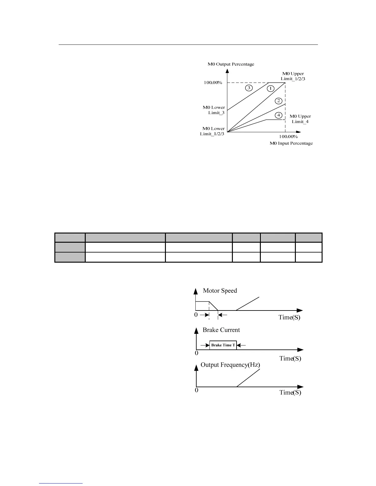
Analog output sets upper limit and lower
limit to meet various needs.
M0 Output Percentage= M0 Lower Limit
+ M0 Input Percentage * M0 Output
Gain* (M0 Upper Limit - M0 Lower
Limit).
Figure 6-11 M0 Output Percentage Curves
4 curves obtained by set relevant M0 output parameters as shown in Figure 6-11:
Curve 1: Set as per the default.
Curve 2: Take curve 1 as the base to adjust M0 output gain.
Curve 3: Take curve 1 as the base to adjust M0 output gain and output lower limit.
Curve 4: Take curve 1 as the base to adjust M0 output gain and output upper limit.
F04 Group: Start/Stop Control Parameters
No. Function Range Unit Default Type
F04.00
DC Brake Current at Start
0.00~150.00
% 0.00
〇
F04.01
DC Brake Time at Start
0.00~30.00
S 0.00
〇
F04.00 sets different values to
achieve various DC brake torques at
start.
F04.01 sets DC brake active time at
start, inverter starts to run
immediately when the time is up. If
F04.01=0.00, DC brake is disabled at
start. See Figure 6-12 for DC brake at
start.
Figure 6-12 DC Brake Process at Start
 Loading...

