© Jan. 2024 34 0608ME All Maintenance Manual
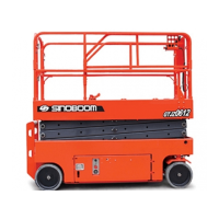
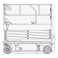
CHASSIS COMPONENT
Drive Motor and Reducer
Disassembly
1. Make sure the machine is in stowed position.
2. Press the main power switch/pull out the main
power handle and disconnect all power sources
(such as battery charger) from the machine.
3. Place a jack of sufficient capacity under the chassis
side to be worked on, and support the chassis.
4. Remove the wheel assembly.
5. Mark and disconnect the harness connections on
the drive motor and reducer.
6. Use suitable lifting equipment to support the drive
motor and reducer.
7. Remove the fasteners of the drive motor and reduc-
er installed on the wheel carrier, and slowly move
the drive motor and reducer out with the assistance
of lifting equipment.
Installation
1. Place a jack of sufficient capacity under the chassis
side to be worked on, and support the chassis.
2. Align the mounting holes on the drive motor and re-
ducer with the ones on the wheel carrier.
3. Fit the flat surface of the gasket to the mounting sur-
face(if a gasket is required), apply Loctite 272 threa-
dlocking adhesive, then install the bolts one by one.
4. Tighten the bolts to the specified torque with a tor-
que wrench.
5. Reconnect the electrical harness.
6. Install the wheel assembly as needed.
Steering Electric Actuator
If the electric actuator has a malfunction, please
contact Sinoboom aftersales staff.
1. Make sure the machine is in stowed position.
2. Place a jack of sufficient capacity under the chassis
to support the chassis.
3. Mark and disconnect the harness connections on
the steering electric actuator.
4. Support the steering electric actuator with suitable
lifting equipment.
5. Remove the cotter pin, gasket and pivot pin secur-
ing the steering electric actuator with the steering
connecting rod.
6. Remove the bolts, stop pin and pivot pin securing
the steering electric actuator to the chassis.
7. Slowly remove the steering electric actuator with the
aid of the lifting equipment.
When disassembling the electric actuator, use
caution to prevent it from falling and getting
damaged.
Installation
1. Place a jack of sufficient capacity under the chassis
to support the chassis.
2. Align the mounting hole on the steering electric ac-
tuator with that on the chassis.
3. Secure the steering electric actuator to the chassis
using the bolts, stop pin and pivot pin.
4. Install the cotter pin, gasket and pivot pin securing
the steering electric actuator with the steering con-
necting rod.
5. Reconnect the electrical harness.
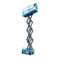
7.2 TIRE ASSEMBLY
Checking Tires and Rims
Maintaining the tires and rims is essential for the normal
and safe operation of the machine. The machine may
tip over if a tire or a rim fails, so check the tires and rims
each time before operating the machine and repair de-
fective tires and rims in a timely fashion.
This machine is equipped with solid tires that do not
need to be inflated.
• Check each tire for cuts, cracks, punctures and ab-
normal wear. Replace the tire if necessary.
• Check each rim for damage, deformation or cracked
welds. Replace the rim if necessary.
Checking Wheel Nuts
The wheel nuts should be tightened before the machine
is put into service for the first time and after each tire is
removed. Check and tighten the wheel nuts to the speci-
fied torque every 3 months or 250 operating hours.