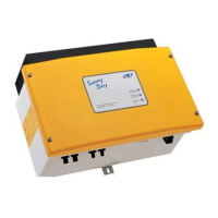
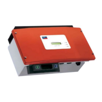
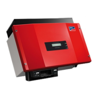
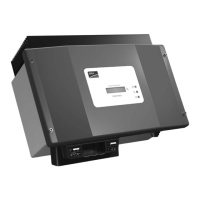
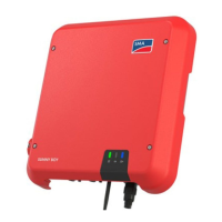
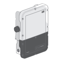
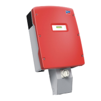
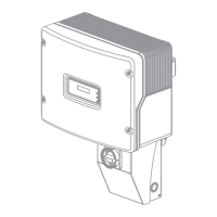
Figure 5: Recommended clearances (dimensions in mm (in))
5.2 Mounting the Inverter
Additionally required mounting material (not included in the scope of delivery):
☐ Two stainless steel hexagon head wood screws (AF10, diameter 6mm), screw length must
be suitable for the support surface and the weight of the inverter (fastening bracket thickness:
4mm)
☐ If necessary, two screw anchors suitable for the support surface and the screws
Risk of injury when lifting the inverter, or if it is dropped
The inverter weighs 9kg. There is risk of injury if the inverter is lifted incorrectly or dropped while
being transported or when attaching it to or removing it from the wall mounting bracket.
• Transport and lift the inverter carefully.
Procedure:
1.
Risk of injury due to damaged cables
There may be power cables or other supply lines (e.g. gas or water) routed in the wall.
• Ensure that no lines are laid in the wall which could be damaged when drilling holes.
2. Mark the position of the drill holes. Align the markings horizontally.
3. Drill the holes.
5 Mounting
SMA Solar Technology AG
Operating Manual 21SB15-25-1VL-40-BE-en-11
 Loading...
