TT301 – Operation & Maintenance Instruction Manual
1.2
Do not remove the graphite grease from the covers, or they may jam.
Electronic Housing
Humidity is fatal to electronic circuits. In areas subjected to high relative humidity, the O-rings for the
electronics cover must be correctly placed. Removal of the electronics cover in the field should be
reduced to the minimum necessary, since each time it is removed; the circuits are exposed to the
humidity.
The electronic circuit is protected by a humidity proof coating, but frequent exposures to humidity may
affect the protection provided. It is also important to keep the covers tightened in place. Every time they
are removed, the threads are exposed to corrosion, since painting cannot protect these parts. Sealing
methods should be employed on conduit entering the transmitter.
One of the conduit inlets for electrical connection is used to mount the sensor integral to the
temperature transmitter (see Fig. 1.1).
The unused cable entries should be plugged and sealed accordingly to avoid humidity entering,
which can cause the loss of the product’s warranty.
For better visibility, the digital indicator may be rotated in steps of 90
o
(see Section 5, Maintenance).
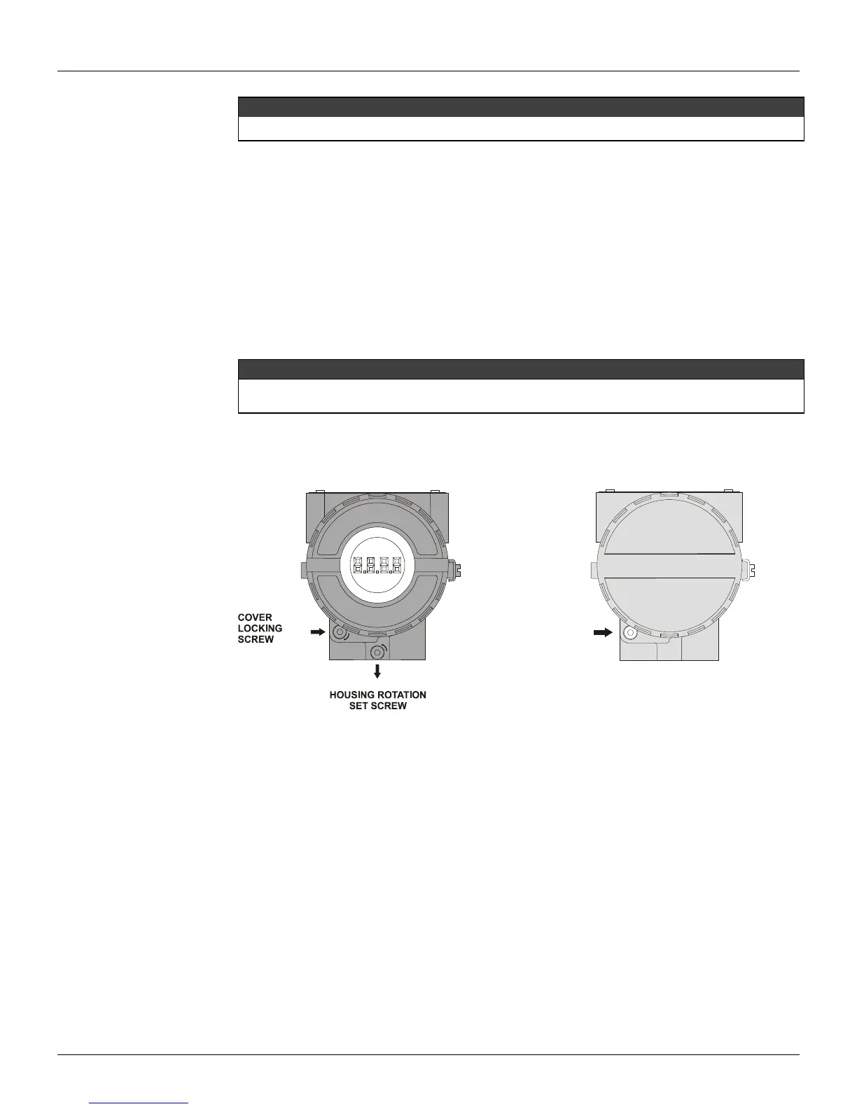
Reach the display and main board by removing the Cover with window. This cover should be locked
closed by the cover locking screw. To release the cover, rotate the locking screw clockwise. See figure
1.2.
Figure 1.2- Cover Locking and Housing Rotating Set Screw (a) Electronic Board Side
(b) Terminal Connection Side
Wiring
Access the wiring block by removing the Electrical Connection Cover. This cover can be locked closed
by the cover locking screw (Figure 1.2- b). To release the cover, rotate the locking screw clockwise.
The terminals in the superior part marked with () and (−) are to receive the powering from 12 to 45
Vdc. The inferior terminals marked with the numbers from 1 to 4 they are for the connections of the
different types of sensor.
Test and Communication terminals allow, respectively, to measure the current in the 4 - 20 mA loop,
without opening it, and to communicate with the transmitter. To measure it, connect a multimeter in the
mA scale in the "" and "" TEST terminals. To communicate with it, use a HART configurator
between "" and "" COMM terminals. The wiring block has screws on which terminals type fork or
ring can be fastened, see Figure. 1.3.