TT301 - Operation and Maintenance Instruction Manual
5.4
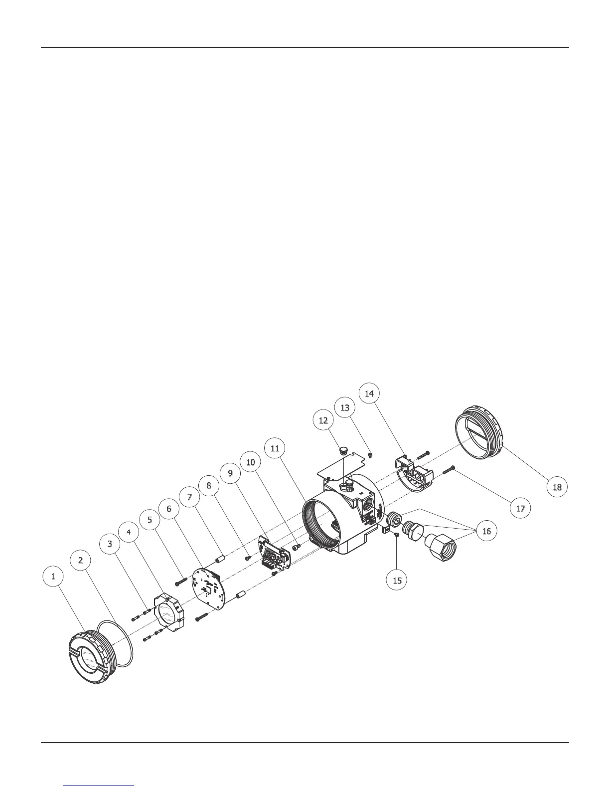
Loosen the two screws (5) that anchor the main circuit board. Gently pull out the main board (6). To
remove the input board (9), first unscrew the two screws (8) that anchors it to the housing (11), gently
pull out the board.
Reassembly Procedure
Put input board (9) into housing (11).
Anchor input board with its screws (8).
Put main board (6) into the housing, ensuring all inter connecting pins are connected.
Anchor main board with their screws (5).
Put display (4) into the housing, observing the four mounting positions (see Figure 5.2) "▲" symbol
should point in the direction desired as UP.
Anchor display with their screws (3).
Fit the cover (1) and lock it using the locking screw (10).
Interchangeability
Calibration data is stored in the EEPROM of the main board, hence READING TRIM must be done if
main-board or input board has been changed.
Returning Materials
Should it become necessary to return the transmitter and/or Configurator to SMAR, simply contact your
local agent or SMAR office, informing the defective instrument's serial number, and return it to our
factory.
In order to expedite analysis and solution of the problem, the defective item should be returned with a
description of the failure observed, with as much details as possible. Other information concerning to
the instrument operation, such as service and process conditions, is also helpful.
Figure 5.1 – Exploded View