Installation
1.3
GROUND
TERMINAL
GROUND
TERMINALS
COMMUNICATION
TERMINALS
TEST
TERMINALS
+
+ +
1 2 3 4
C
O
M
M
T
E
S
T
Figure 1.3 - Ground Terminal
The TT301 is protected against reversed polarity.
For convenience there are three ground terminals: one inside the cover and two external, located close
to the conduit entries.
Use of twisted pair (22 AWG) cables is recommended.
Avoid routing signal wiring close to power cables or switching equipment.
The Figure 1.3 shows the correct installation of the conduit, in order to avoid penetration of water, or
other substance, which may cause malfunctioning of the equipment.
Figure 1.4 - Conduit Installation Diagram.
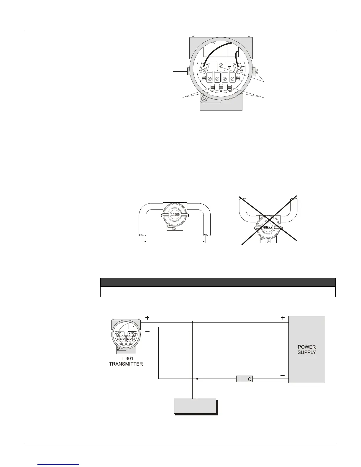
Loop Connections
Do not connect the Power Supply to the sensor terminals (Terminals 1, 2, 3 and 4).
Connection of the TT301 working as transmitter should be performed as in Figure 1.6.
Figure 1.5 – Wiring Diagram for the TT301 Working as Transmitter
Connection of the TT301 working as a controller (Optional) should be as indicated in Figure 1.5.