TT301 – Operation & Maintenance Instruction Manual
1.4
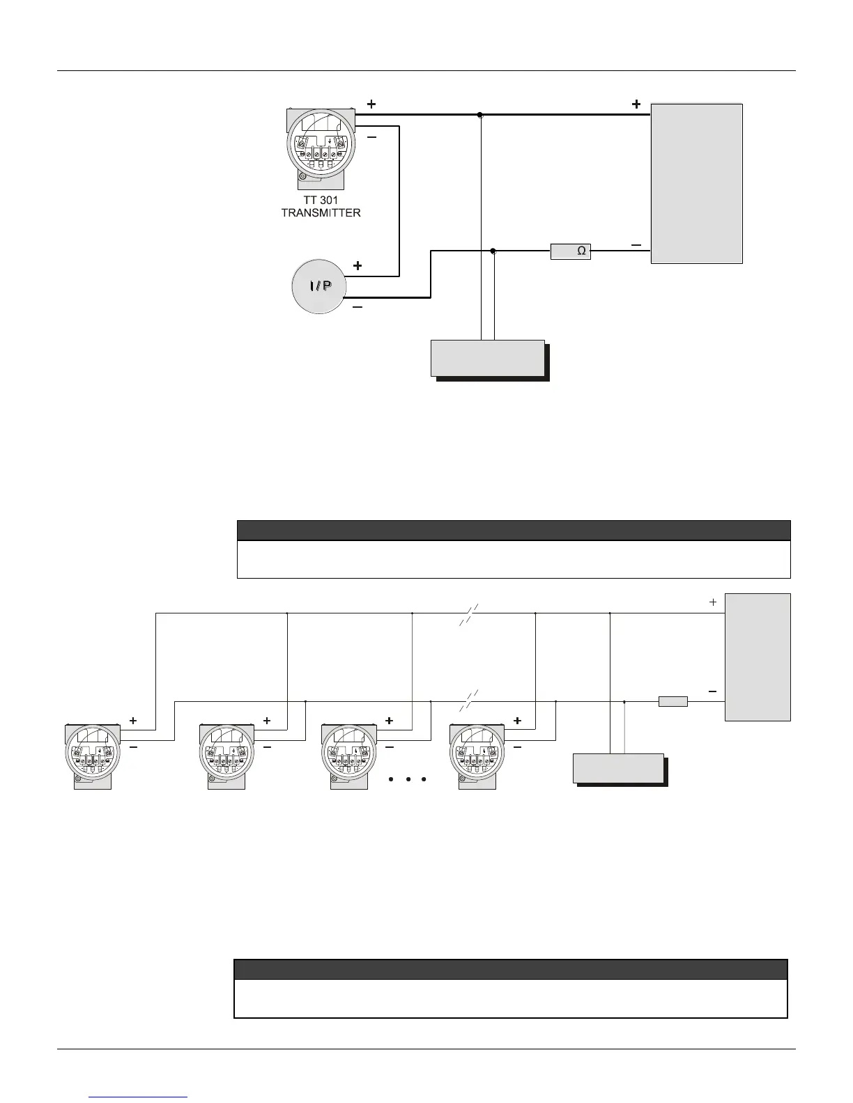
CONFIGURATOR
POWER
SUPPLY
250
Figure 1.6 – Wiring Diagram for the TT301 Working as Controller
Connection of the TT301 in multidrop configuration should be done as in Figure 1.6. Note that a
maximum of 15 transmitters can be connected on the same line and that they should be connected in
parallel. When many transmitters are connected to the same line, calculate the voltage drop through
the 250 Ohm resistor and verify that the voltage of the power supply is enough (Figure 1.7).
Wiring diagram for the TT301 in multidrop.
For proper operation, the configurator requires a minimum load of 250 Ohm between it and the
power supply.
TT301
# 2
TRANSMITTER
TT301
# 3
TRANSMITTER
TT301
# 15
TRANSMITTER
POWER
SUPPLY
250
CONFIGURATOR
TT301
TRANSMITTER
# 1
Figure 1.7 - Wiring Diagram for the TT301 in Multidrop Configuration
The Configurator can be connected to the communication terminals of the transmitter or at any point of
the signal line by using the interface with alligator clips.
It is also recommended to ground the shield of shielded cables at only one end. The not grounded end
must be carefully isolated.
Make sure that the transmitter is operating within the operating area as shown on the load diagram
(Figure 1.9). Communication requires a minimum load of 250 Ohm.