TT301 - Operation & Maintence Instruction Manual
3.6
Conection and Work Model
After the selection of the sensor type is necessary to choose the way how sensors work. The available
options are: differential, 2 wires, 3 wires, 4 wires, backup, average, maximum and minimum. In the
options 2, 3 or 4 wires, only one sensor is connected in the device terminal. In the options differential,
backup, average, maximum and minimum are connected 2 sensors.
2, 3 and 4 wires: only one sensor will go to generate the process variable. If it ruptures, the burnout
indication will be showed.
Differential: In this mode, the TT301 will go to work with the measure difference between the sensors.
If one of them to ruptures, the burnout indication will be showed.
Backup: TT301 works with the reading of the first sensor (between 2 and 4 terminals). If this sensor
brokes, the second sensor (between 3 and 4 terminals) will replace it and show the process variable
reading. In this case, the reading of the first sensor will be discarded, even if this sensor returns to
operate again. The first sensor will back to operate again if either gives it a reset by software or
reenergize the device again. The message “S1BAD” will appear on LCD and the HART response code
“Non-PV out of limits” is set. In case of failure of the second sensor, the transmitter will continue to
operate normally but the message “S2BAD” will appear on LCD and the HART response code “Non-PV
out of limits” will be set.
Average: the final reading will be the average of the signals from two sensors. If the difference between
them is higher than a programmed value, an alarm will be generated. If one of them ruptures, the other
continues performing the process variable reading, and an alarm will be generated to inform this
situation. The message “S1BAD” or “S2BAD” will appear on LCD and the HART response code “Non-
PV out of limits” will be set.
Maximum and minimum: the process variable will be supplied by sensor that has either maximum or
minimum reading, respectively. If one of them ruptures, the other continues performing the process
variable reading, and an alarm will be generate to inform this situation. The message “S1BAD” or
“S2BAD” will appear on LCD and the HART response code “Non-PV out of limits” will be set.
Special Sensor Configuration
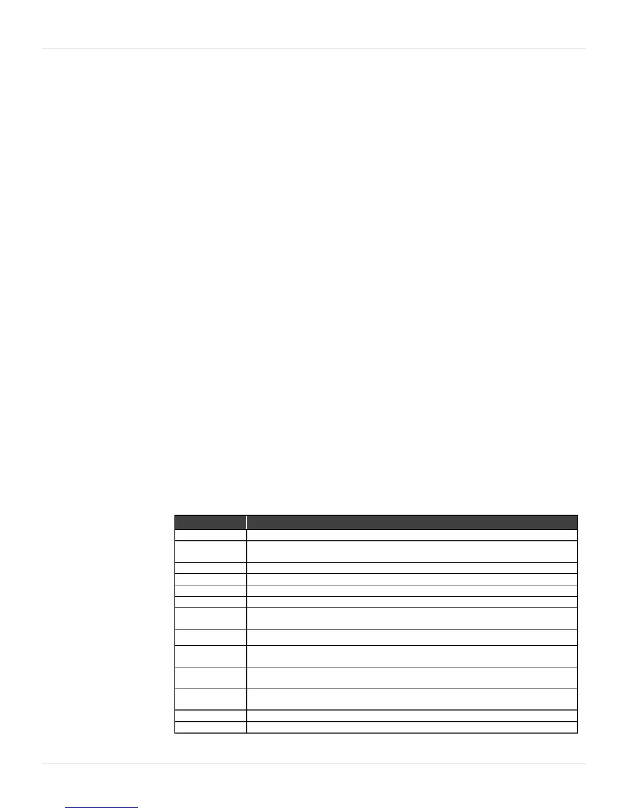
The special sensor is a function that permits sensors whose typical curves are not stored in the TT301
memory to be used or linearized. Table 3.1 shows the available units for special sensors.
Any sensor may be used, provided the TT301 accepts the signal range generated by the sensor. The
Ohm and mV sensors limitations may be seen on table 3.2.
To change the special sensor configuration select special on the sensor menu.
inH
2
O, InHg, ftH
2
O, mmH
2
O, mmHg, psi, bar, mbar, g/cm
2
, Pa, KPa,Ton, ATM
ft
3
/min, gal/min, l/minin, Gal/min, m
3
/h, gal/s, l/s, Ml/d. ft/
3
s, ft
3
/d, m
3
/s, m
3
/d,
Gal/h, Gal/d, ft
3
/h, m
3
/min, bbl/s, bbl/min, bbl/h, bbl/d, gal/h, Gal/s, l/h
gal, l, Gal, m
3
, bbl, bush, Yd
3
, ft
3
, In
3
gram, Kg, Ton, lb, Shton, LTon
g/s, g/min, g/h, kg/s, kg/min, kg/h, kg/d, Ton/min, Ton/h, Ton/d, lb/s, lb/min, lb/h,
lb/d, Ton/d
SGU, g/cm
3
, kg/m
3
, g/ml, kg/l, g/l, TWARD, BRIX, Baum H, Baum L, API, %
Solw, % Solv, Ball
Ohm, Hz, mA, %, pH, s, cPo
Table 3.1 – Special Sensor Available Units