Operation
2.7
R
V2
2
1
+
-
3
4
R
RTD
TRANSMITTER
I
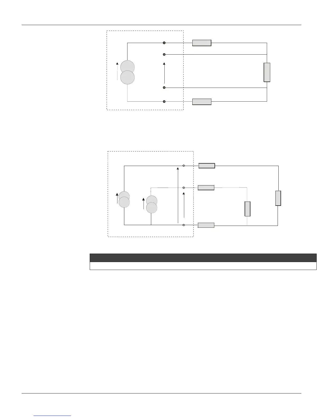
Figure 2.5 – Four-Wire Connection
A differential connection is similar to the two-wire connection and gives the same problem (see Figure
2.6). Terminal 3 is a high impedance input. Thus, no current flow through and no voltage drop is
caused, but the resistance of the other two wires will be measured and does not cancel each other out
in a temperature measurement, since linearization will affect them differently.
TRANSMITTER
1,3
R
R
R
2
4
V1
V2
RTD2
RTD1
I
I
Figure 2.6 – Differential Connection
The material, the gauge, and the length should be the same connections of 3 or 4 threads.
The Display
The digital indicator is able to display one or two variables which are user selectable. When two
variables are chosen, the display will alternate between the two with an interval of 3 seconds.
The different fields and status indicators are explained in Figure 2.7.
Monitoring
During normal operation, the TT301 is in the monitoring mode. In this mode, indication alternates
between the primary and secondary variable as configured in DISPLAY. See Figure 2.8.
The display indicates engineering units, values and parameters simultaneously with most status
indicators. The monitoring mode is interrupted in two situations:
User performs complete local adjustment.
An alarm is activated.