TT301 – Operation and Maintenance Instruction Manual
2.6
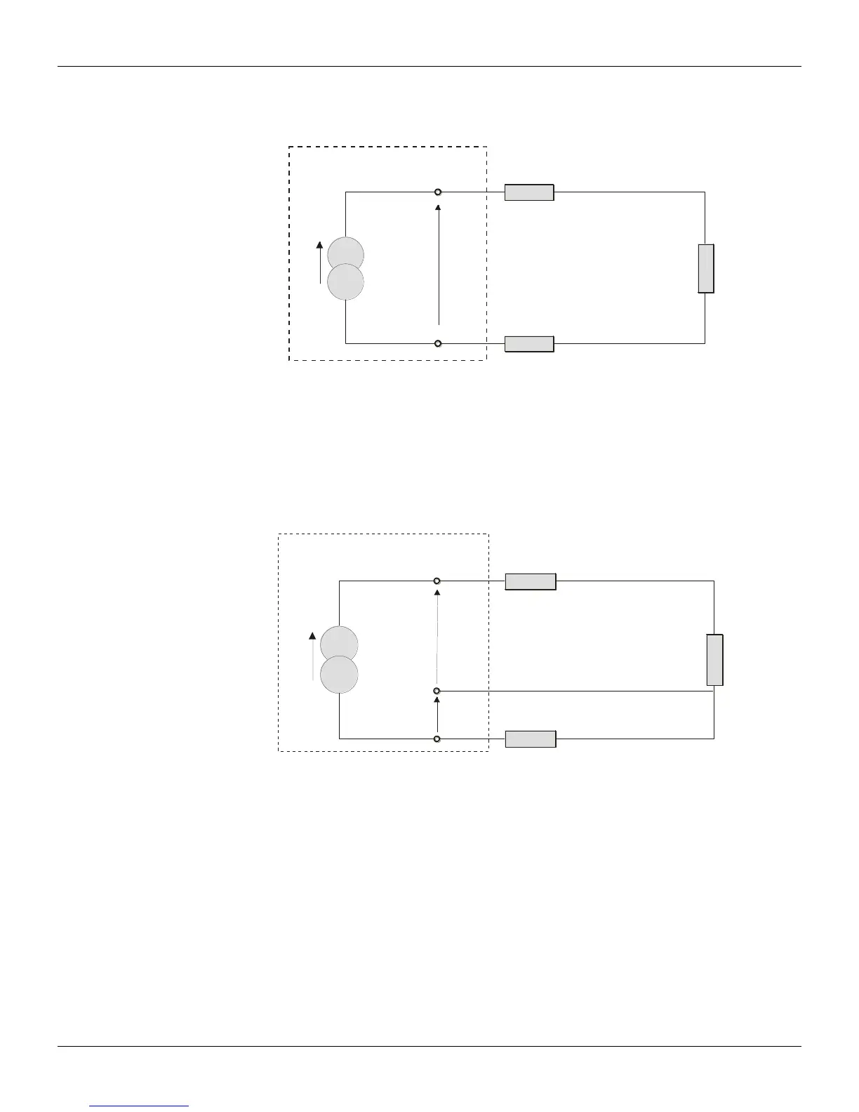
In a 2-wire connection, the voltage V2 is proportional to the RTD resistance plus the resistance of the
wires.
V2 = [RTD + 2x R] x I
R
V2
TRANSMITTER
2,1
3,4
R
RTD
I
Figure 2.3 – Two-Wire Connection
In order to avoid the resistance effect of the connection wires, it is recommended to use a 3-wire
connection (see Figure 2.4) or a 4-wire connection (see Figure 2.5).
In a 3-wire connection, terminal 3 is a high impedance input. Thus, no current flows through that wire
and no voltage drop is caused. The voltage V2-V1 is independent of the wire resistances since they will
be canceled out, and is directly proportional to the RTD resistance alone.
V2-V1 = [RTD + R] x I - Rx I = RTDx I
R
V2
V1
TRANSMITTER
2,1
4
3
R
RTD
I
Figure 2.4 – Tree-Wire Connection
In a 4-wire connection, terminals 2 and 3 are high impedance inputs. Thus, no current flows through
those wires and no voltage drop is caused. The resistances of the other two wires are not interesting
since no measurement is done on them. Hence the voltage V2 is directly proportional to the RTD
resistance. (V2 = RTD x I).