20
4 Connectors
4.1 Overview
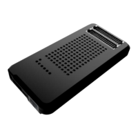
FlashRunner LAN 2.0 Next Generation connects to your programming/testing system
through:
▪ “ISP” connectors: 48 way, 3 rows, DIN 41612, pitch = 2.54mm (male)
▪ “ATE CONTROL” connector: 14 way, 2 rows, pitch = 1.27mm (male)
▪ Additionally, a micro USB and Ethernet connectors are provided to interface fully
with the ATE system.
4.2 ISP Connectors
“ISP” connectors group signals needed to program up to 4 target devices. These
connectors are type R/2 DIN41612 (TE part number 5650479-5) with several
input/output lines and power lines.
Note: ISP and I/O signals are not optoisolated and are referenced to GND
(power supply ground).
Additionally, in order to avoid undesired current loops between
FlashRunner LAN NXG power supply and target board, a power supply
with a floating output (ground not referenced to the earth potential) should
be used.