25
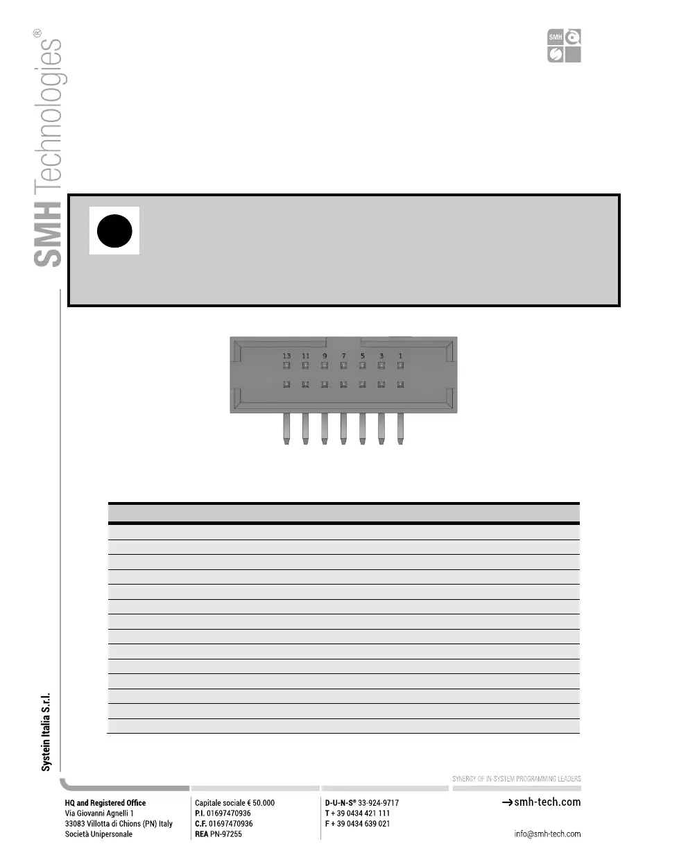
4.3 ATE Control Connector
ATE Control Connector is used to communicate with the host system and for
integration with automatic programming/testing equipment (ATE).
Note: all control signals are referenced to GND_I, separate from GND.
This allows a host system to safely communicate with FlashRunner LAN
2.0 Next Generation even when the target boards have different ground
reference compared to the host system’s (and it’s not possible to connect
them together).
Figure 7: ATE CONTROL Connector
Table 6: Control Connector Signals
Project selection 0 (input, referenced to GND_I)
5V output (output, fuse-protected, referenced to GND_I)
Project selection 1 (input, referenced to GND_I)
Programming channel 1 PASS/FAIL (output, referenced to GND_I)
Project selection 2 (input, referenced to GND_I)
Programming channel 2 PASS/FAIL (output, referenced to GND_I)
Project selection 3 (input, referenced to GND_I)
Programming channel 3 PASS/FAIL (output, referenced to GND_I)
Project selection 4 (input, referenced to GND_I)
Programming channel 4 PASS/FAIL (output, referenced to GND_I)
Selected Project START (input, referenced to GND_I, active low)
Selected Project BUSY (output, referenced to GND_I, active low)