22
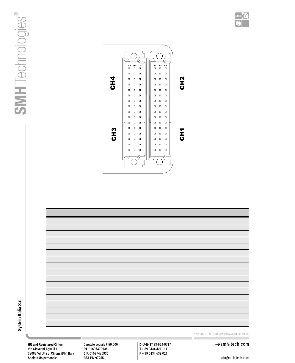
Figure 6: ISP Connector
Table 4: ISP Connector Signals (Channels 1 and 2)
ISP Channel 2: Programmable voltage 0
ISP Channel 2: Programmable voltage 1 Ground
ISP Channel 2: Digital input/output 1
ISP Channel 2: Digital input/output 2 Ground
ISP Channel 2: Digital input/output 4
ISP Channel 2: Digital input/output 5 Ground
ISP Channel 2: Digital input/output 7
ISP Channel 2: Relay Barrier Power Source
ISP Channel 1: Relay Barrier Power Source
ISP Channel 1: Programmable voltage 0
ISP Channel 1: Programmable voltage 1 Ground
ISP Channel 1: Digital input/output 1
ISP Channel 1: Digital input/output 2 Ground
ISP Channel 1: Digital input/output 4
ISP Channel 1: Digital input/output 5 Ground
ISP Channel 1: Digital input/output 7
ISP Channel 2: Programmable voltage 0 Ground