30
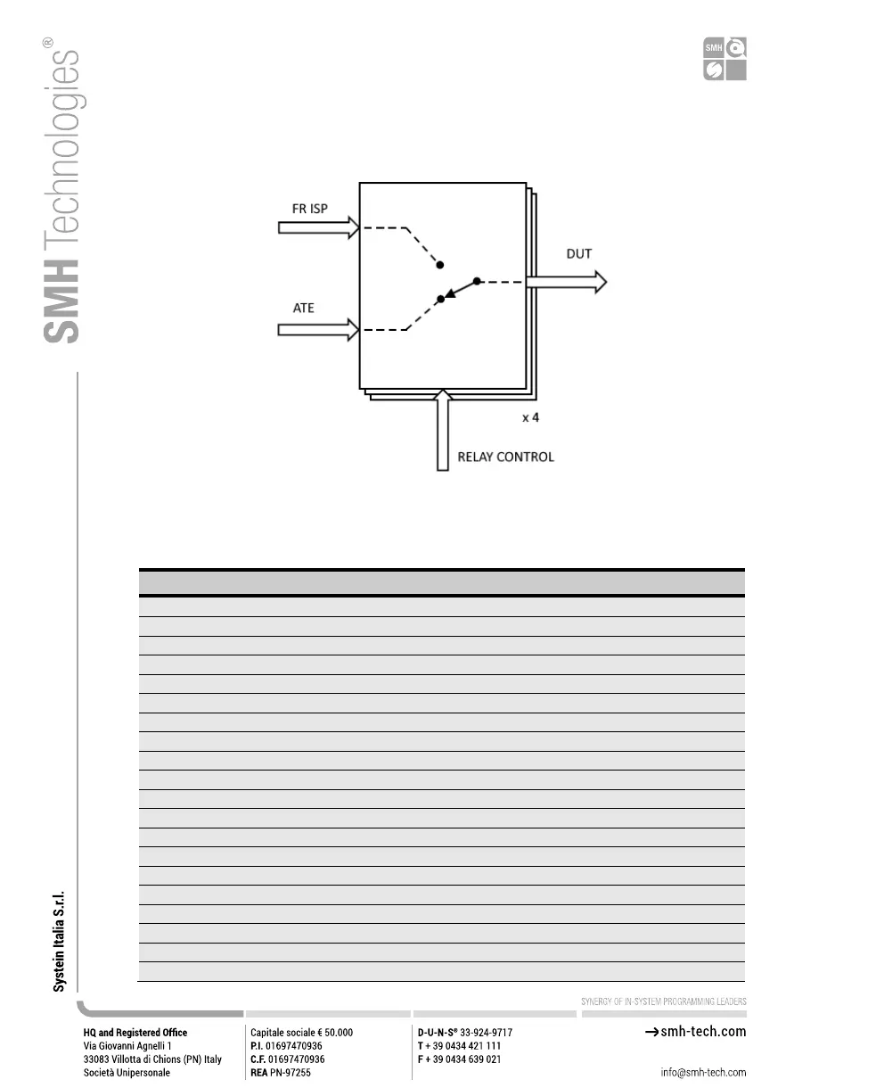
Block diagram of the ISP lines switching capabilities:
Figure 12: Relay Barrier Application Note
Table 8: Auxiliary Connector Pinout
ISP Channel A: Digital input/output 0
ISP Channel B: Digital input/output Vprog0
ISP Channel A: Digital input/output 1
ISP Channel B: Digital input/output VProg1
ISP Channel A: Digital input/output 2
ISP Channel B: Digital input/output Ground 0
ISP Channel A: Digital input/output 3
ISP Channel B: Digital input/output Ground 1
ISP Channel A: Digital input/output 4
ISP Channel B: Digital input/output 0
ISP Channel A: Digital input/output 5
ISP Channel B: Digital input/output 1
ISP Channel A: Digital input/output 6
ISP Channel B: Digital input/output 2
ISP Channel A: Digital input/output 7
ISP Channel B: Digital input/output 3
ISP Channel A: Digital input/output VProg0
ISP Channel B: Digital input/output 4
ISP Channel A: Digital input/output VProg1
ISP Channel B: Digital input/output 5