ISP Channel B: Digital input/output 4 Ground
ISP Channel B: Digital input/output 3
ISP Channel B: Digital input/output 1 Ground
ISP Channel B: Digital input/output 0
ISP Channel B: Programmable voltage 0 Ground
ISP Channel A: Digital input/output 6 Ground
ISP Channel A: Digital input/output 5
ISP Channel A: Digital input/output 3 Ground
ISP Channel A: Digital input/output 2
ISP Channel A: Digital input/output 0 Ground
ISP Channel A: Programmable voltage 1
ISP Channel A: Relay Barrier Ground
ISP Channel B: Relay Barrier Ground
ISP Channel B: Digital input/output 6 Ground
ISP Channel B: Digital input/output 5
ISP Channel B: Digital input/output 3 Ground
ISP Channel B: Digital input/output 2
ISP Channel B: Digital input/output 0 Ground
ISP Channel B: Programmable voltage 1
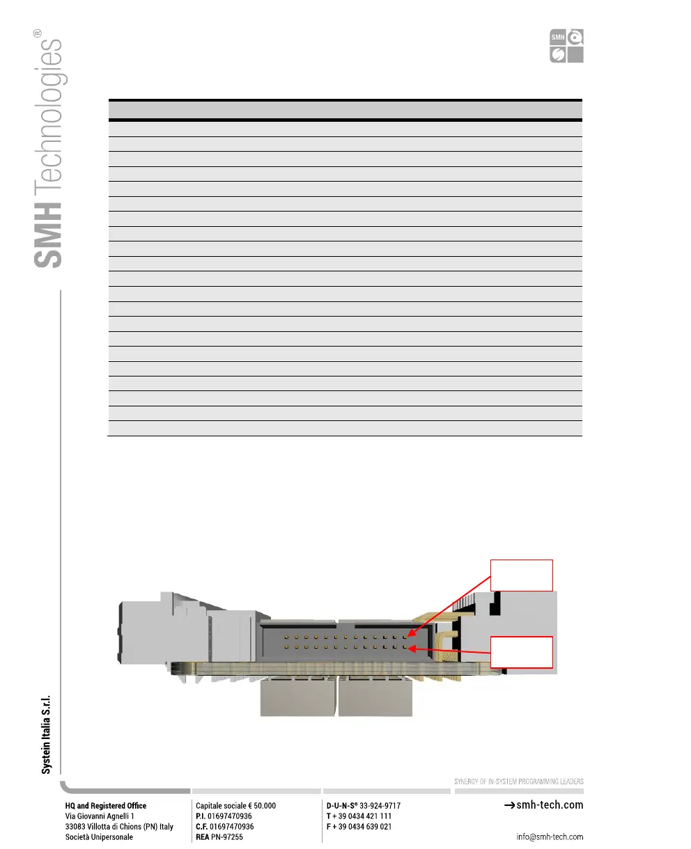
A 26 pins auxiliary input connector is available onboard, which connects to the output
pins of the two channels when the relays are open.
You can use the provided Auxiliary Interface board to connect your signals to the UUT
when not using the programmer’s digital IOs.
Figure 11: FRLAN2P0NXGRB Auxiliary input connector