UPS/NTA GB/DMX-DMP JBUS.D Page 3 / 22
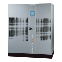
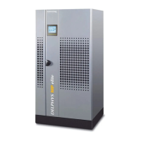
JBUS/MODBUS SERIAL INTERFACE INSTALLATION INSIDE DELPHYS MX / MP
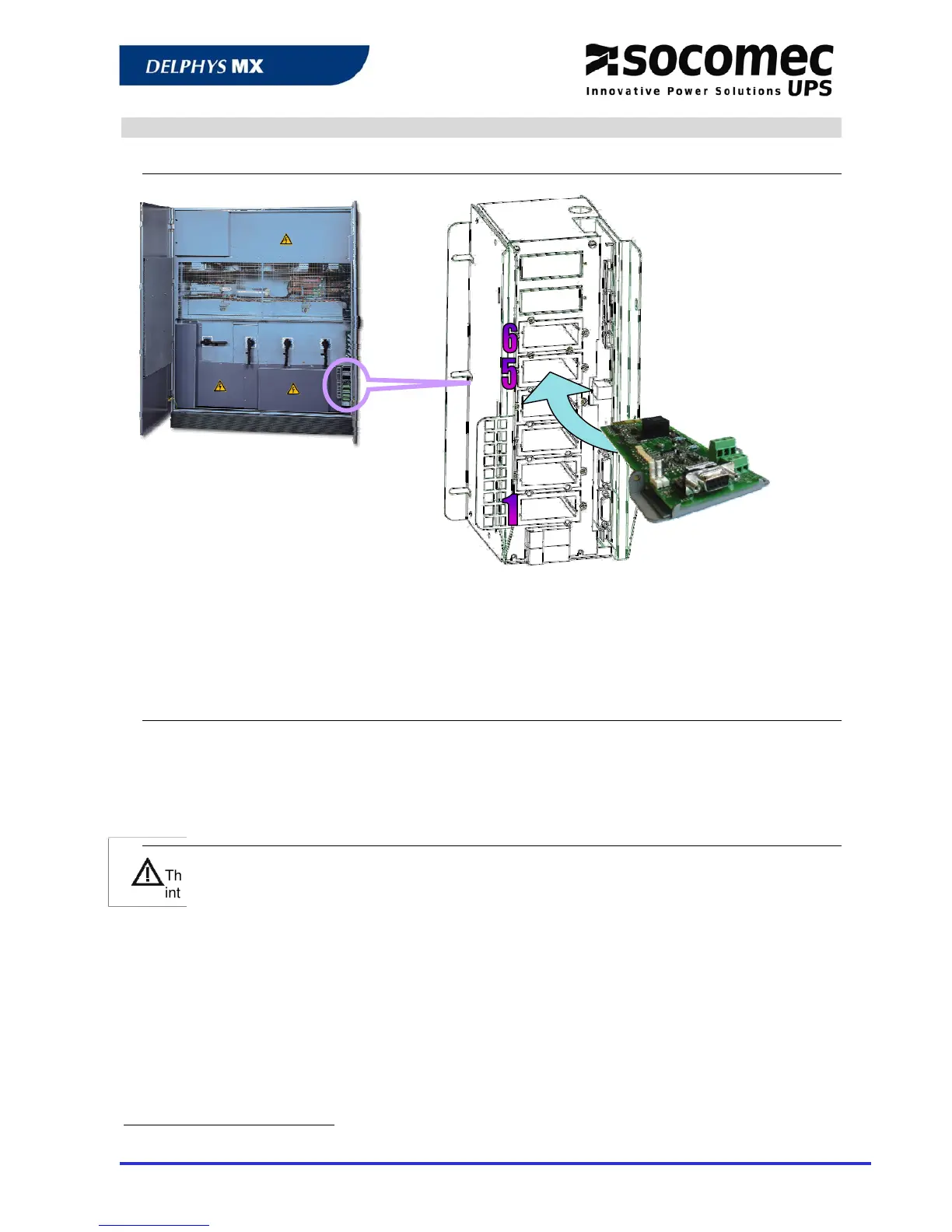
‘Com-Slots’ localisation
The « Com-Slots » integrates all communication interfaces, and it is located at the bottom of the UPS, on
the right side.
Slots 5 and 6 are dedicated to
J
J
B
B
U
U
S
S
/
/
M
M
O
O
D
D
B
B
U
U
S
S
serial
interfaces.
Slots 1 to 4 are used for the alarm report boards, 3 inputs and 4 programmable relays (ADC).
JBUS/MODBUS serial interface plug in
The serial interface should be plugged in the corresponding slot, and fixed with 2 crews.
DELPHYS MX / MP is able to manage up to 2 independent
J
J
B
B
U
U
S
S
/
/
M
M
O
O
D
D
B
B
U
U
S
S interfaces. Each interface can
be set differently, like the slave numbers.
JBUS interface in parallel system configuration
There is only one
J
J
B
B
U
U
S
S
/
/
M
M
O
O
D
D
B
B
U
U
S
S serial link interface for a parallel system configuration. One serial
interface is used for the whole installation. The access to the data of the UPS module or unit is
managed by the table addressing
1
.
1
See chapter 5