11
MAN_Sigma_16_GB_00
03/2016
Manuel d'entretien et d'utilisation
user maintenance guide
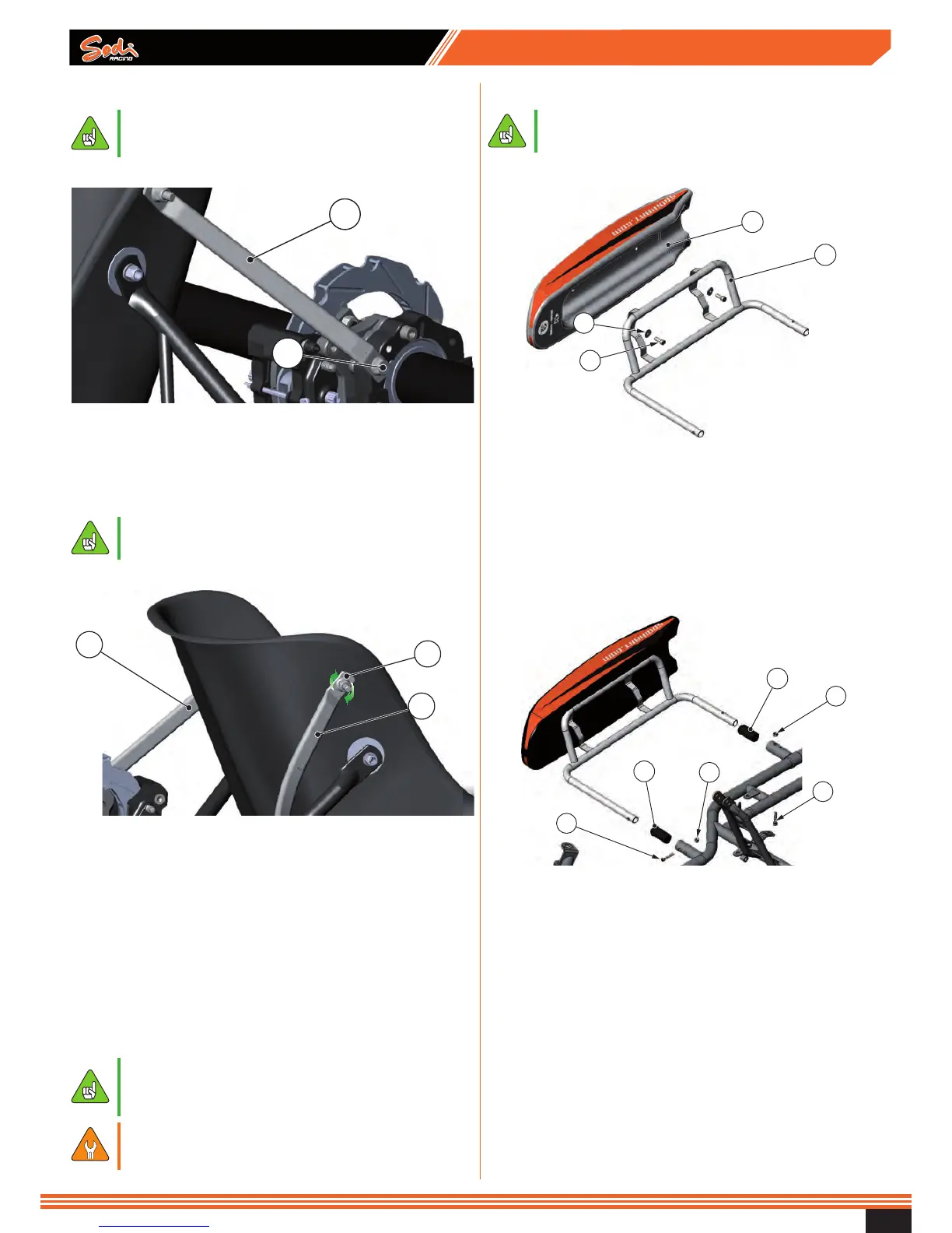
3.7 - Assembly of the seat stiffeners
● See chapter “standard settings” for the
assemblies’ dimensions which correspond to the
standard setting recommended for your frame.
Lower end
1
2
Legend
1 Seat stiffener
2 Screw
● Put the seat stiffener lower end (1) in place.
● Pre-tighten the assembly with the screw (2).
● For screws and nuts references, refer to the spare
parts.
Upper end
1
2
1
Legend
1 Seat stiffener
2 Screw + conical washer + nut
● Place the upper end of the stiffener.
● Make sure there is no contact with the exhaust system and
with any part of the engine.
If necessary, slightly bend the stiffener.
● Drill a 8.5 mm diameter hole in the seat.
● Place one screw + conical washer (2).
● Tighten both upper and lower end.
● Apply the same procedure to mount the stiffener on the left
side of the seat.
● For screws and nuts references, refer to the spare
parts.
● For other types of stiffeners, refer to the spare
parts and the web site ITAKA.
● It is possible to install several seat stiffener
(left and right).
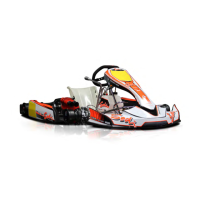
3.9 - Assembly of the bodywork
● For screws and nuts references, refer to the spare
parts.
Step 1
1
2
3
4
Legend
1 Side pod
2 Side pod support
3 Screw
4 Washer
● Place the side pod (1) on the side pod support (2).
● Tighten the side pod (1) with the screws (3). Remember to
include the washers (4).
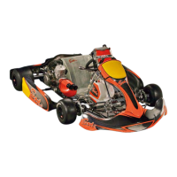
Step 2
1
3
2
2
3
1
Legend
1 Bushing
2 Screw
3 Nut
● Insert the bushings (1) in the nozzles on the frame.
● Insert the assembly into the bushings (1).
● Drill the bushings (1) using the holes as a guide and
tighten the assembly with the screws (2) and nuts (3).