Function IEEE 1547 Default Settings Range
OLRT 5 1-90 seconds
Active Power-Reactive
power mode
(1)
Disabled
P3 1 0.5-1 nameplate power p.u.
P2 0.5 0.4-0.8 nameplate power p.u.
P1 0.2 0-0.7 nameplate power p.u.
P'1 -0.2 -0.7-0 nameplate load p.u.
P'2 -0.5 -0.4-(-0.8) namplate load p.u.
P'3 -1 -1-(-0.5) namplate load p.u.
Q3 -0.44 +/- 1 nameplate Var p.u.
Q2 0 +/- 1 nameplate Var p.u.
Q1 0 +/- 1 nameplate Var p.u.
Q'1 0 +/- 1 nameplate Var p.u.
Q'2 0 +/- 1 nameplate Var p.u.
Q'3 0.44 +/- 1 nameplate Var p.u.
Voltage Active power
mode
(1)
Disabled
V1 1.06 1.05-1.09 V p.u.
P1 1 nameplate power p.u.
V2 1.1 1.06-1.10 V p.u.
P2 0 0-1 namplate power p.u.
P'2 0 -1-0 nameplate load p.u.
OLRT 10 0.5-60 seconds
Frequency-droop mode Disabled
DBOF 0.036 0-1 Hz
DBUF 0.036 0-1 Hz
KOF 0.05 0.02-0.07
KUF 0.05 0.02-0.07
OLRT 5 0.2-10 seconds
(1)
Load parameters P' and Q' apply to single phase energy storage inverters only.
Appendix E: Interconnection Standards101
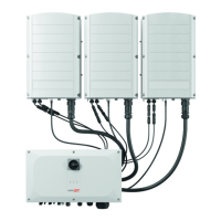
Three Phase Inverters with Synergy Technology PN: SExxK-xxxxIxxxx
Normal Ramp Rate
(2)
100 1-100%/ seconds
(2)
California rule 21 function.

 Loading...