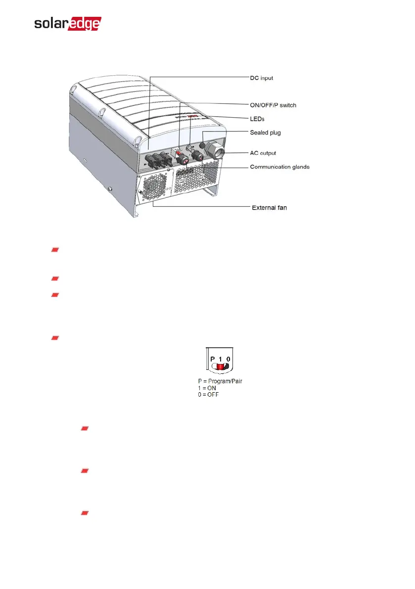
Figure 5: Inverter Interfaces
ACoutput: ACoutput gland, AC cable external gauge, M32 (15-21mm diameter)
for connection to the grid
DC input: MC4 connector ,for connection of the PV installation
Two communication glands: for connection of inverter communication
options. Each gland has three openings. Refer to
Setting Up Communication
on
page 49 for more information.
ON/OFF/P Switch:
Figure 6: ON/OFF/P switch
ON (1) - Turning this switch ON (after optimizer pairing) starts the
operation of the power optimizers, enables power production and
allows the inverter to begin exporting power to the utility grid.
OFF (0) - Turning this switch OFF reduces the power optimizer voltage
to a low safety voltage and inhibits exportation of power. When this
switch is OFF, the control circuitry remains powered up.
P - Moving and releasing the switch allows viewing system information
Chapter 3: Installing the Inverter 21
Three Phase System Installation Guide MAN-01-00505-1.2