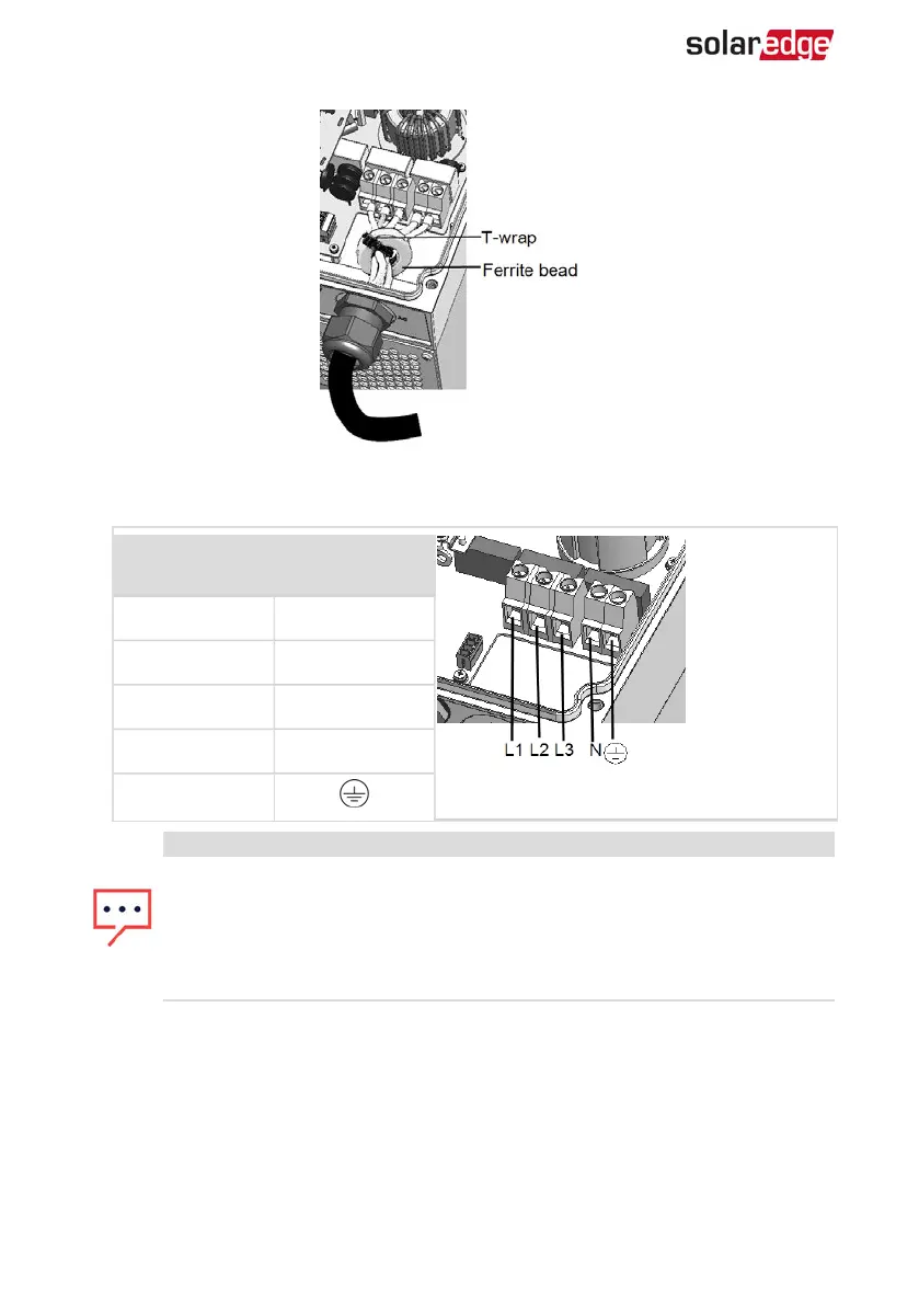
Figure 14: Attaching a Ferrite bead
6.
Connect the AC, as follows. Connect the PE (grounding) wire first.
Wire type
Connect to
terminal
Figure 15: AC Terminals
Line 1 L1
Line 2 L2
Line 3 L3
Neutral N
PE (grounding)
NOTE
If power control is enabled, it is important to respect the order of grid lines
connection to the inverter. A 120deg phase difference should be kept
between L1 to L2 and between L2 to L3 (L1-L2-L3 and not, for example L1-L3-
L2).
If the grid lines are not in this order, an error is displayed on the SetApp
screen and the inverter will not produce power.
7. Connect the wires to the appropriate terminal block connectors in the inverter.
Tighten the terminal block screws with a torque of 1.2-1.5 N*m / 0.88-1.1 lb*ft.
8. Check that the wires are fully inserted and cannot be pulled out easily.
9. Tighten the AC cable gland with a torque of 2.8-3.3 N*m / 2.0-2.4 lb*ft.
10. Verify that there are no unconnected wires to the inverter and that the unused
terminal screws are tightened.
-Three Phase System Installation Guide MAN-01-00505-1.2
32 Connecting the ACGrid to the Inverter