3
CONNECTING
TO THE SI1287
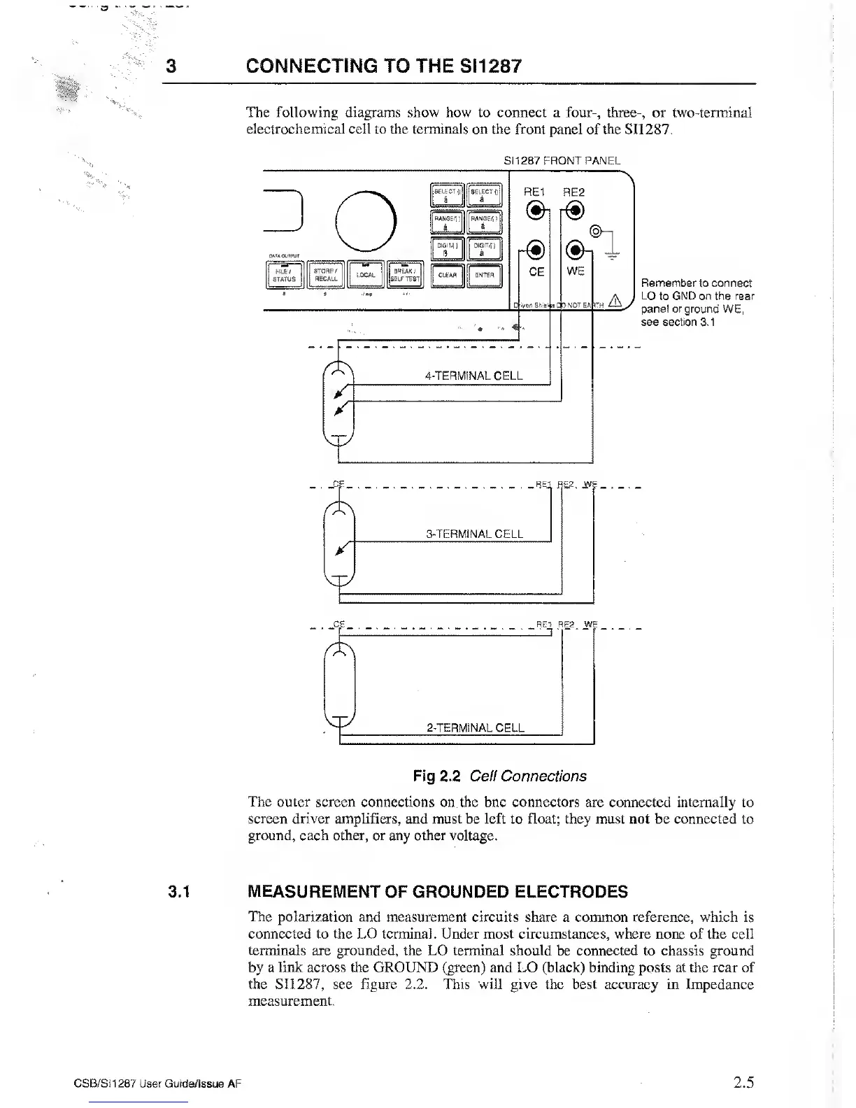
The following diagrams
show how to connect a four-, three-, or two-terminal
electrochemical cell to the terminals on the front panel of the SI1287.
SATA OL'H'UI
j
PILE/
STATUS
S1
1287 FRONT PANEL
STORE /
RECALL
BREAK
/
iSELF TEST
SELECT
0
a
a
RANGE.!
)
RANGE*)
a
a
—
DIGIT*
J
DIGIT*}
8
a
|
CLEAR ENTER
RE1
RE2
&
CE
4-TERMINAL CELL
r®
®-i
®i
I
WE
th Ay
Remember to connect
LO to GND on the rear
panel or ground
WE,
see
section 3.1
Cj=_ . _8
ei
RE2. jyy
3-TERMINAL CELL
*
_CE_
.
_R£.T RE2. WE
2-TERMINAL CELL
Fig 2.2 Cell
Connections
The
outer
screen
connections on the bnc connectors are connected internally to
screen driver amplifiers, and must be left to float; they must not
be connected to
ground, each other, or any other voltage.
3.1 MEASUREMENT
OF GROUNDED ELECTRODES
The
polarization and measurement circuits share a common reference, which is
connected to the LO terminal. Under most circumstances, where none
of
the cell
terminals are grounded, the LO terminal should
be connected to chassis ground
by a
link
across
the
GROUND (green) and LO (black) binding posts at the rear of
the
SI1287,
see figure 2.2. This will give the best accuracy in Impedance
measurement.
CSB/SI1287
User Guide/Issue AF
2.5