9
PLOT
The measurement results
may be
plotted
on a suitable digital plotter
via
the GPIB
port of
SI1287.
Note: During plotting,
set the
DATA
OUTPUT {GPIB} menu to [off], to prevent
corruption
of the signals to the plotter.
9.1
{X ITEM}
> >
Remote command is XI/. Refer to Chapter
4,
Section
6.2 1
.
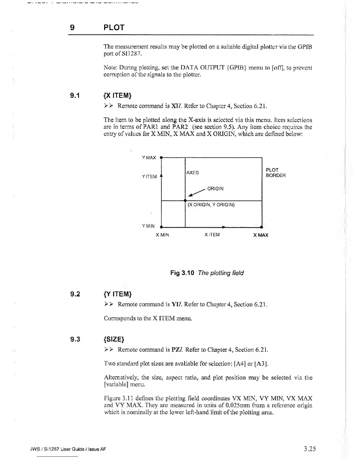
The item
to be
plotted
along the X-axis is selected via this menu. Item
selections
are in
terms of PARI and PAR2 (see section
9.5).
Any item choice requires
the
entry of values for X MIN, X MAX and
X ORIGIN, which are defined below:
Fig 3.10 The plotting field
9.2
{Y ITEM}
> >
Remote command is YI7. Refer to Chapter
4,
Section 6.2 1
.
Corresponds to the
X ITEM menu.
9.3
{SIZE}
> >
Remote command is PZ/. Refer
to Chapter
4,
Section 6.2 1
.
Two
standard plot sizes are available for selection: [A4]
or [A3].
Alternatively, the size, aspect ratio, and
plot position may be selected via the
[variable] menu.
Figure 3.11 defines the plotting field coordinates
VX MIN, VY MIN, VX MAX
and VY MAX. They are measured in units of
0.025mm from a reference origin
which
is
nominally
at
the
lower left-hand limit of the plotting area.
JWS
/ S1
1287 User
Guide / Issue AF
3.25