3
GPIB INTERFACE
3.1 GPIB
CAPABILITY
CODES
The capability
of a
device
interface can
be identified by the series
of
alphanumeric codes, which normally appear against the bus connector. The
alphabetic
part of the codes
represent
a basic
interface function, such
as a talker
or
listener, whilst the numeric part represents the capability
of
that function.
The
GPIB
Interface in the instrument conforms to the
following sub-functions
within the standard,
as
listed on the rear panel:
SH1 Source handshake
.
AH1 Acceptor handshake.
T5 Basic talker. Serial poll, Talk only selectable, unaddressed if MLA
(My Listener Address).
TEO No Extended talker
capability.
L4 Basic listener,
no
listen only mode, unaddressed if MTA
(My Talker Address).
LEO
No
extended listener capability.
SRI Complete service request capability.
RL1 Complete Remote/Local capability, with Local Lock-Out.
PP2
Parallel
poll with Local
configuration.
DC1 Complete device clear capability, including selective device clear.
CO No controller capability.
DTO No device trigger capability.
E1
Open
Collector
drivers
.
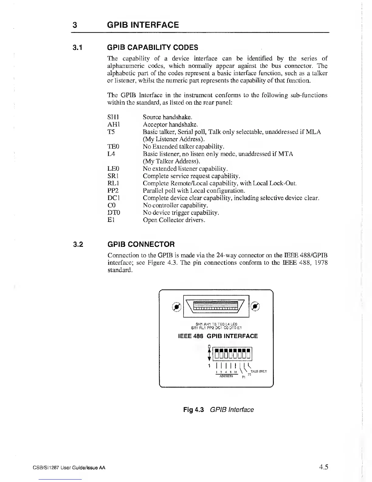
3.2 GPIB CONNECTOR
Connection to the GPIB
is
made via the 24-way connector on the IEEE 488/GPIB
interface; see
Figure 4.3.
The pin
connections conform
to
the IEEE
488,
1978
standard.
Fig 4.3
GPIB Interface
CSB/SM287 User Guide/Issue
AA
4.5