ui lapici
\J
whether
the cell will be disconnected
(standby), when
the sweep ends or
is
stopped by the user.
8.3
{SEGMENTS}
> >
Remote
command is SMF. Refer
to Chapter
4,
Section
6.13.
This menu
selects the number of segments,
ie. distinct ramps,
or ’staircases’ to
be
applied to the cell during
the sweep. After segment number
4 the cycle begins
to
repeat itself.
8.4
{VI
RMP}
> >
Remote
command is VAF to VDF. Refer
to Chapter
4,
Section 6.14.
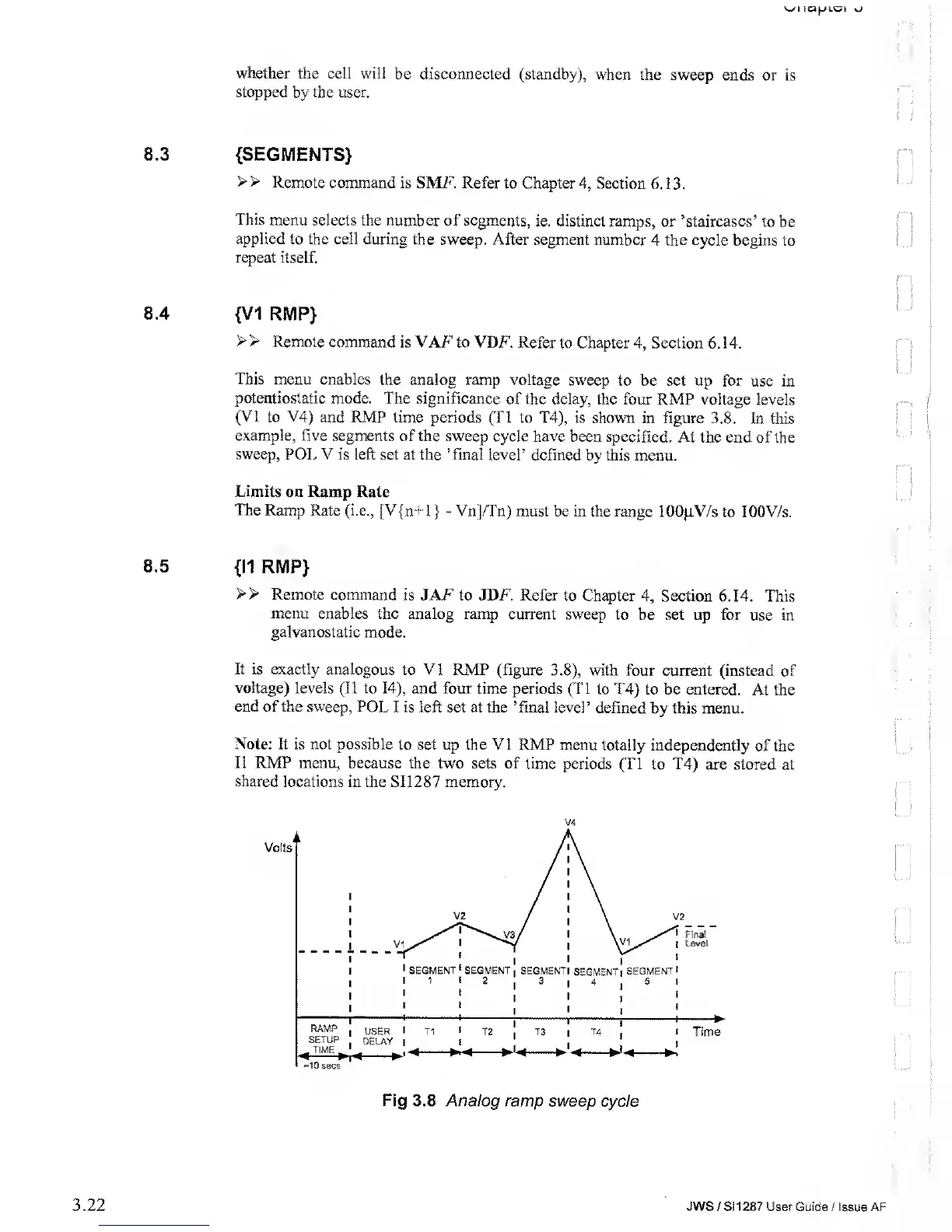
This
menu enables
the analog ramp voltage sweep
to be set
up for use in
potentiostatic
mode.
The
significance
of the delay, the four
RMP voltage levels
(VI
to V4) and RMP
time periods (T1 to T4), is
shown in figure
3.8. In this
example, five
segments of the sweep
cycle have been specified.
At the end of
the
sweep,
POL V is left set at the ’final level’
defined by this
menu.
Limits on
Ramp Rate
The Ramp Rate (i.e., [V{n+1
}
-
Vn]/Tn) must be in
the range 1 00}iV/s
to lOOV/s.
8.5
{II RMP}
>>
Remote command
is
JAF to JDF. Refer to Chapter
4,
Section 6.14.
This
menu enables
the analog ramp current sweep to
be set
up for use in
galvanostatic
mode.
It is exactly analogous
to
VI
RMP (figure
3.8),
with
four current (instead
of
voltage) levels (II
to
14),
and four
time periods (Tl to T4)
to be entered. At the
end
of the sweep, POL
I is left set at the ’final level’
defined by this menu.
Note: It is
not possible
to set up the VI RMP menu totally
independently of the
II RMP
menu, because
the two sets of time periods
(Tl to T4) are
stored at
shared locations
in the SI 12
87
memory.
V4
Fig 3.8 Analog ramp sweep
cycle
3.22
JWS
/ S!
1 287
User Guide / Issue AF