8.6
{VI STP}
> >
Remote command
is SAF to SDF.
Refer to Chapter
4,
Section
6. 15.
This menu enables
the
digitally
stepped
voltage sweep to be set
up
for
use in
potentiostatic
mode.
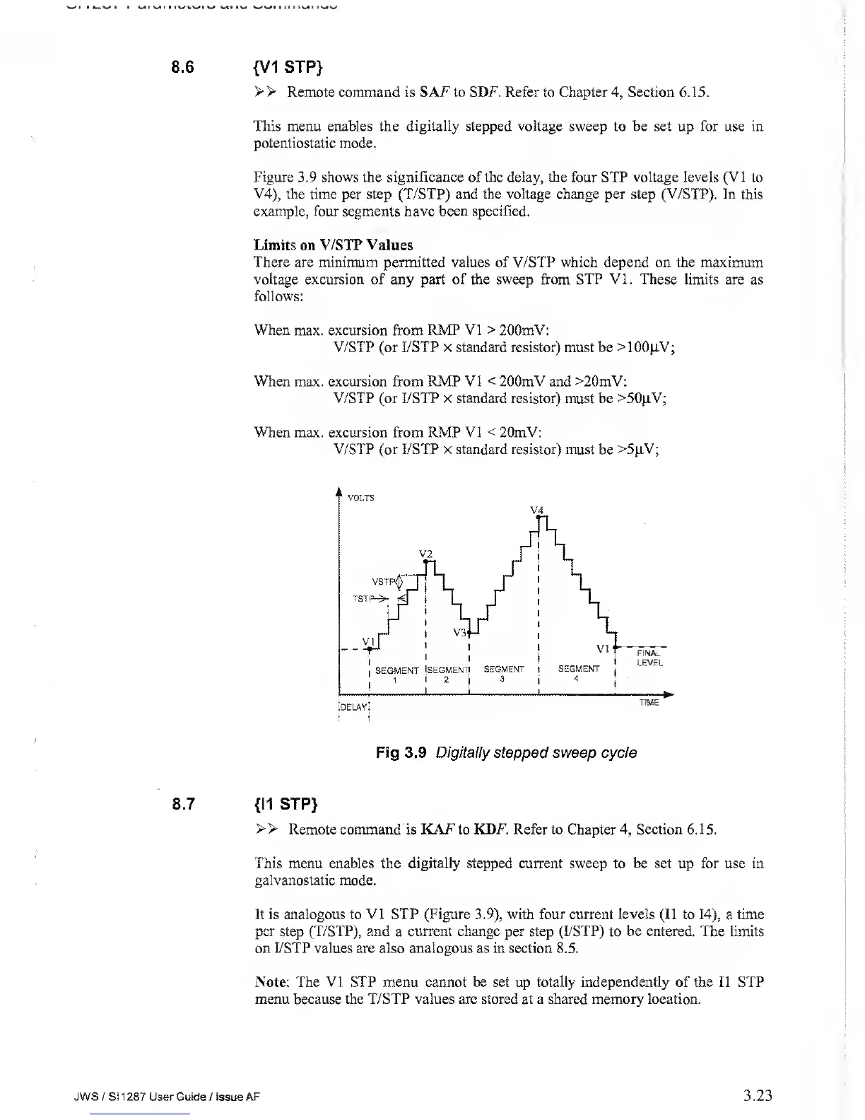
Figure
3.9 shows the
significance of the
delay,
the four STP voltage
levels
(VI
to
V4),
the time per step (T/STP) and the voltage change per step (V/STP). In this
example, four segments have been specified.
Limits on V/STP Values
There are minimum permitted values of V/STP which depend on
the
maximum
voltage excursion of any part
of
the sweep from STP VI. These limits are as
follows:
When max. excursion from
RMP VI
>
200mV:
V/STP (or I/STP
x
standard resistor) must be >100|iV;
When max. excursion from RMP VI
<
200mV and >20mV:
V/STP (or
I/STP
x
standard resistor) must be >50jTV;
When max. excursion from RMP VI
<
20mV:
V/STP (or
I/STP
x standard resistor) must
be
>5jiV;
Fig 3.9 Digitally stepped
sweep cycle
8.7
{II STP}
> >
Remote command is
KAF
to
KDF.
Refer to Chapter
4,
Section 6. 1 5.
This menu enables the digitally stepped current sweep to be set up for use in
galvanostatic mode.
It is analogous to VI STP (Figure
3.9),
with four current levels (II to
14),
a
time
per
step
(T/STP), and
a
current change per step
(I/STP) to
be entered. The
limits
on I/STP values are also analogous
as
in section 8.5.
Note: The VI STP menu cannot be set up totally independently of the II STP
menu because the
T/STP
values are stored at a shared memory location.
JWS
/ Si
1 287
User
Guide
/
issue AF
3.23