28
Figure 5 14 Checking the voltage of every route Strings.
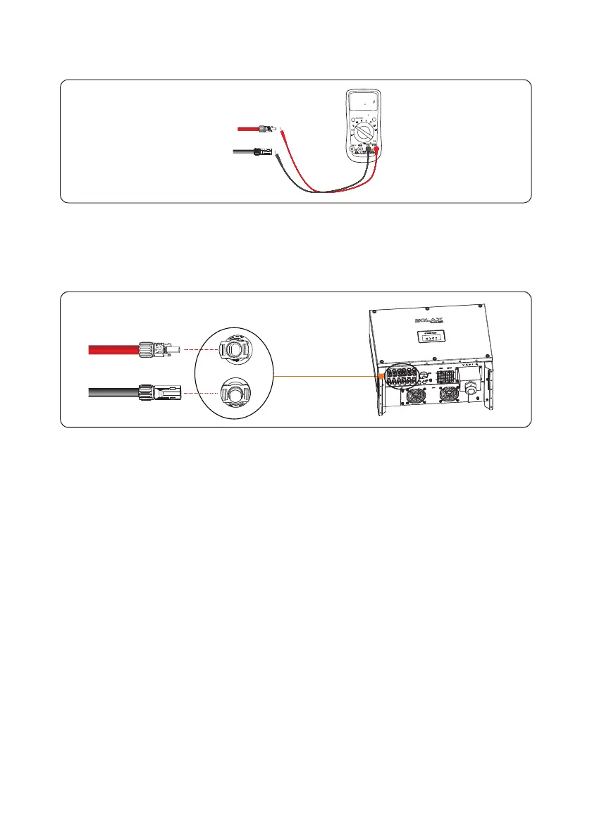
Step 6 Insert the positive and negative connectors into their corresponding terminals of the
inverter until a click sound is heard as shown in Figure 5 15" " , . .
Step 7 After connecting the PV strings ensure that all connectors are in position by checking,
for resistance when a slight pull is applied.
Figure 5 15 Connecting to the inverter.
RANGE
MAXMIN REL
Hz %
10A
MAX
hFE
COM
!
!!
FUSED
FUSED
PC
800 00
PV-
PV+
PC

 Loading...


