27
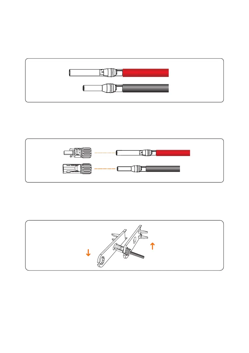
Step 2 Insert the exposed areas of the positive and negative power cables into the metal
terminals of the positive and negative connectors respectively and crimp them using a crimping
tool, as shown in Figure 5.11.
Figure 5.11 Crimping a metal connector
Step 3 Insert the crimped positive and negative power cables into the corresponding positive
and negative connectors until a "click" sound is heard, as shown in Figure 5.12.
Figure 5.12 Connecting positive and negative connectors
Step 4 Tighten the locking nuts on the positive and negative connectors using a removal
wrench, as shown in Figure 5.13.
Figure 5.13 Locking connectors
Step 5 Measure the voltage of every route Strings using a multimeter. Ensure that the polarities
of the DC input power cables are correct, as shown in Figure 5.14.

 Loading...


