6. Operation
User Manual
38
6. P-Factor
Description: Inverter will change power factor based on changing output power.
Note: This Setting is NOT required by UL1741SB Standards.
This function is for maintenance personnel only, wrong operation
will prevent the inverter from reaching maximum power.
5. Reac-Power
Description: Inverter will generate reactive power based on changing output power.
Range: -60%~+60%
Default: 0%
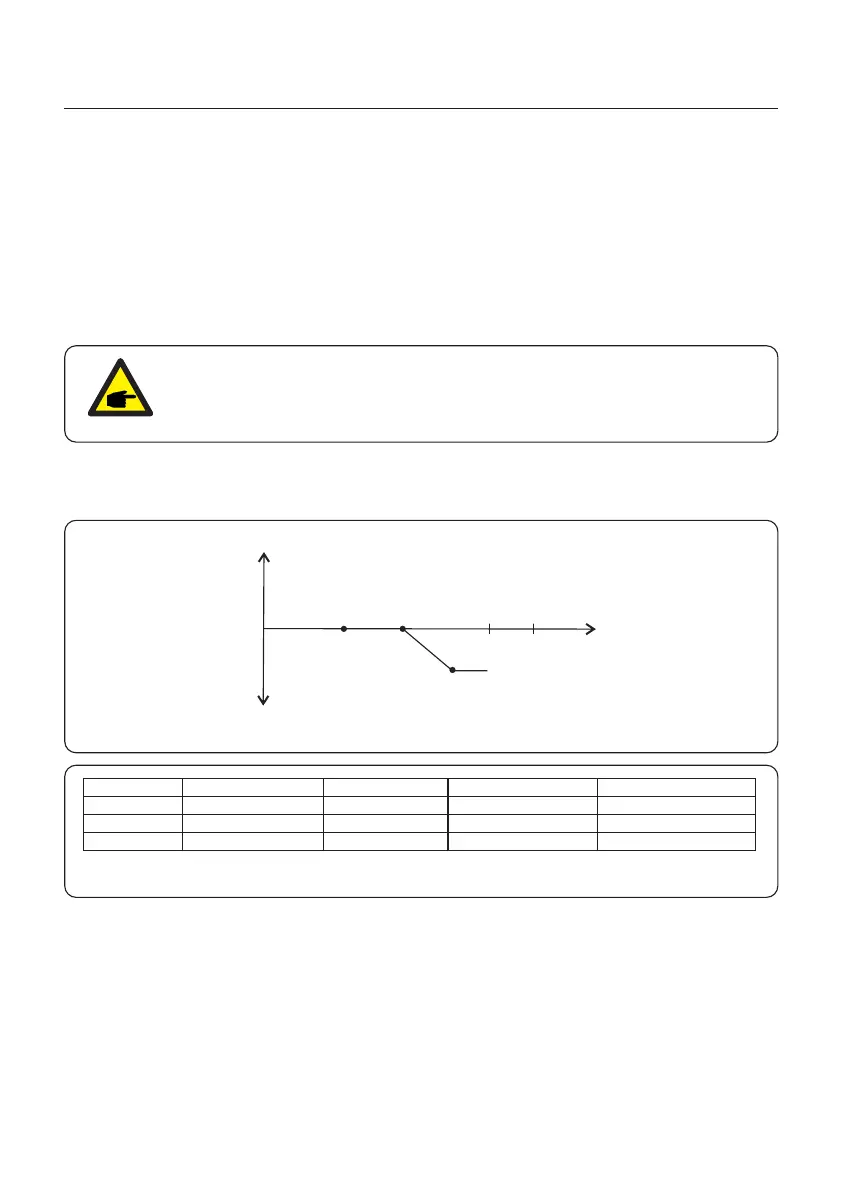
7. P-Q Mode
Description: Inverter will change reactive power based on active power output.
Figure 6.28
Reactive Power
Injection/Over Excited
Absorption/Under Excited
(0,0) (P1,Q1) (P2,Q2)
(P3,Q3)
Active Power
(Generation)
P3
Setting Point
P/Q 1
Active Power Default Active Power range
Table 6.7
Reactive Power Default
0
0
-44%Sn
Reactive power Range
-60%Sn~60%Sn
P/Q 2
P/Q 3
Prated
0.2 Prated
0.5 Prated
0.5 Prated~Prated
0.4 Prated~0.8 Prated
0~0.7 Prated
-60%Sn~60%Sn
-60%Sn~60%Sn






 To Next Page