The inverter is designed in accordance with the most important international grid-tied
standards and safety and electromagnetic compatibility requirements. Before delivering
to the customer, the inverter has been subjected to several tests to ensure its optimal
operation and reliability.
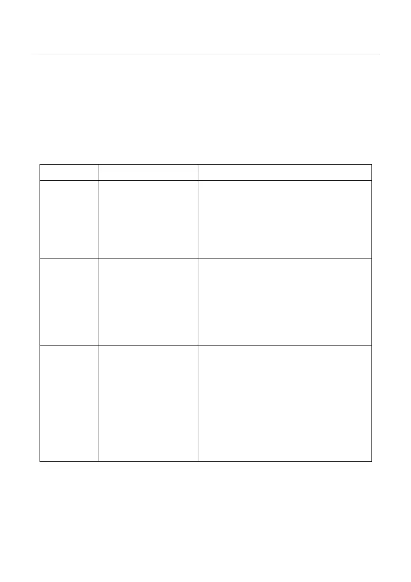
In case of failure, the LCD screen will display an alarm message. In this case, the inverter
may stop feeding into the grid. The failure descriptions and their corresponding alarm
messages are listed in Table 8.1:
Alarms
Cause Solution
• Input voltage low/missing
• Polarity reversed
• Main board damaged
No Information
(Blank Screen)
Test – DC switch OFF
• Check PV connections
• Check polarity
• Check voltage >120V Single, >350V three
Test – DC Switch ON
• Check voltage >120V Single, >350V three
• If DC voltage is “0” replace inverter
Initializing
(Inverter stuck
in this mode)
• Inverter is waiting for
driving signal
Test – DC switch OFF
• Check PV connections
• Check polarity
• Check voltage >120V Single, >350V three
Test – DC Switch ON
• Check voltage >120V Single, >350V three
• A cable may have been damaged or loosened
in shipping replace inverter
OV-G-V: Over
Grid Voltage
• Inverter detects grid
voltage as too high
Test – DC switch OFF
• Check AC at the inverter
• If AC measures high, adjust upper limit with
permission from utility
Test – DC Switch ON, full power
• Check AC at inverter test points
• Compare with LCD
• If AC measures high, cables between inverter
and interconnect are too small
• Check ampacity and voltage drop calculations
• Verify appropriate Grid Standard
8. Troubleshooting
User Manual
51

 Loading...