User Manual
D
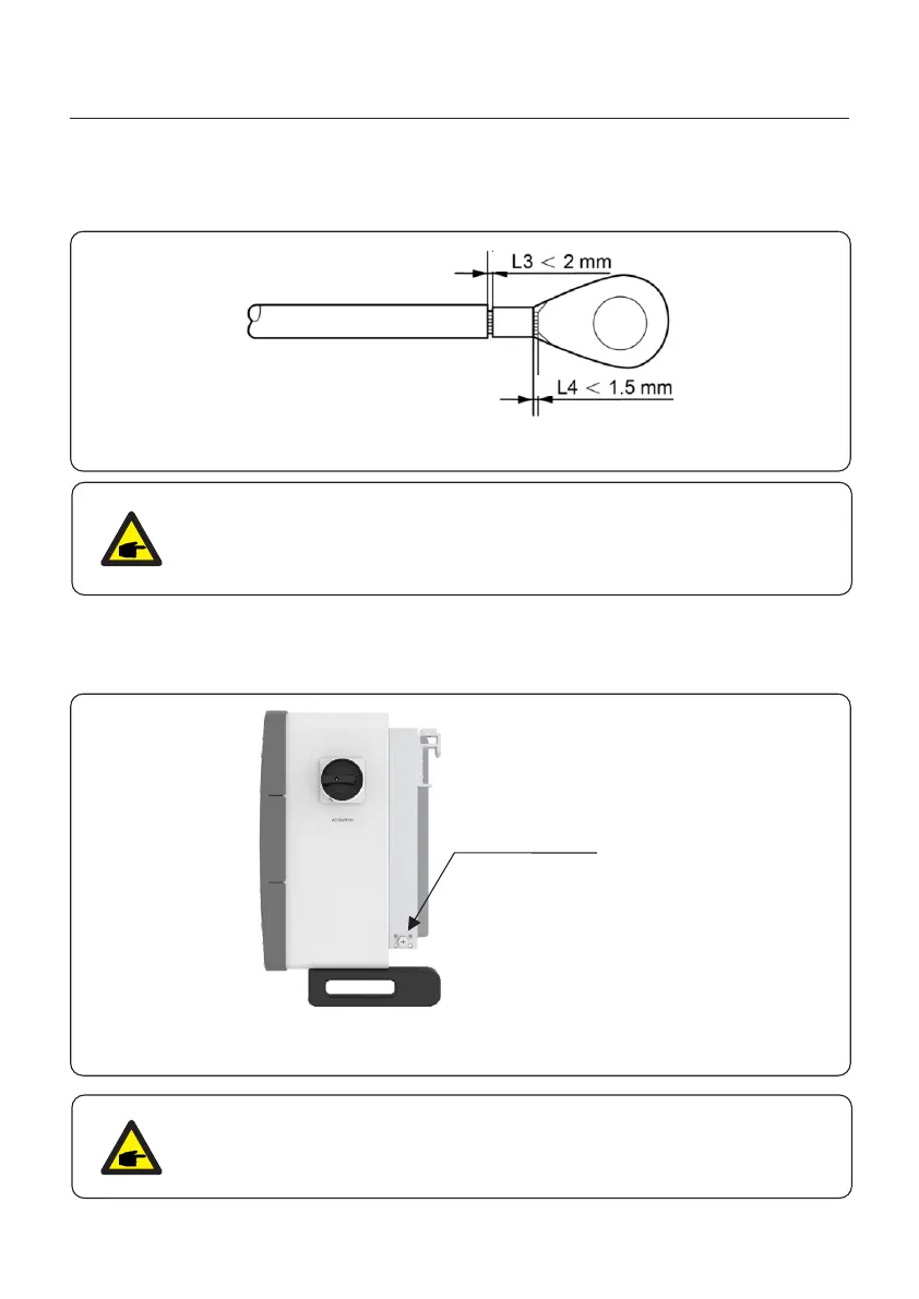
C
Grounding screw
Figure 3.17 Strip wire
NOTE
After crimping the terminal to the wire, inspect the connection to ensure the
terminal is solidly crimped to the wire.
5. Remove the M10 screw from the heat sink ground point.
Figure 3.17 Fixed cable
For improving anti-corrosion performance, after ground cable installed,
apply anti oxidizing grease.
NOTE
4. Insert the stripped wire into the OT terminal crimping area and crimp with a hydraulic
crimp tool. (see Figure 3.17)
6. Connect the grounding cable to the grounding point on the heat sink, and tighten the
grounding screw, Torque is 4.4-6.0 ft.lbs. (see figure 3.17)
3. Installation
22