MPI-520 OPERATING MANUAL version 3.4
the installation; PE lead is connected to the phase lead) and generates a continuous audio signal.
This possibility is available for all measuring functions that apply to residual current devices (RCD)
and short circuit loop.
Remarks:
WARNING:
When phase voltage is detected on PE lead, measurements must be immediately
stopped and a fault in the installation must be removed.
- The person making a measurement must ensure that he/she is standing on a non-insulated floor
during the measurement; otherwise the result of the measurement may be incorrect.
- The threshold value, which triggers the signal of exceeded allowable voltage on PE conduit, is ap-
proximately 50 V.
3.3 Measurement of current, active power, reactive power, apparent
power and cosφ coefficient
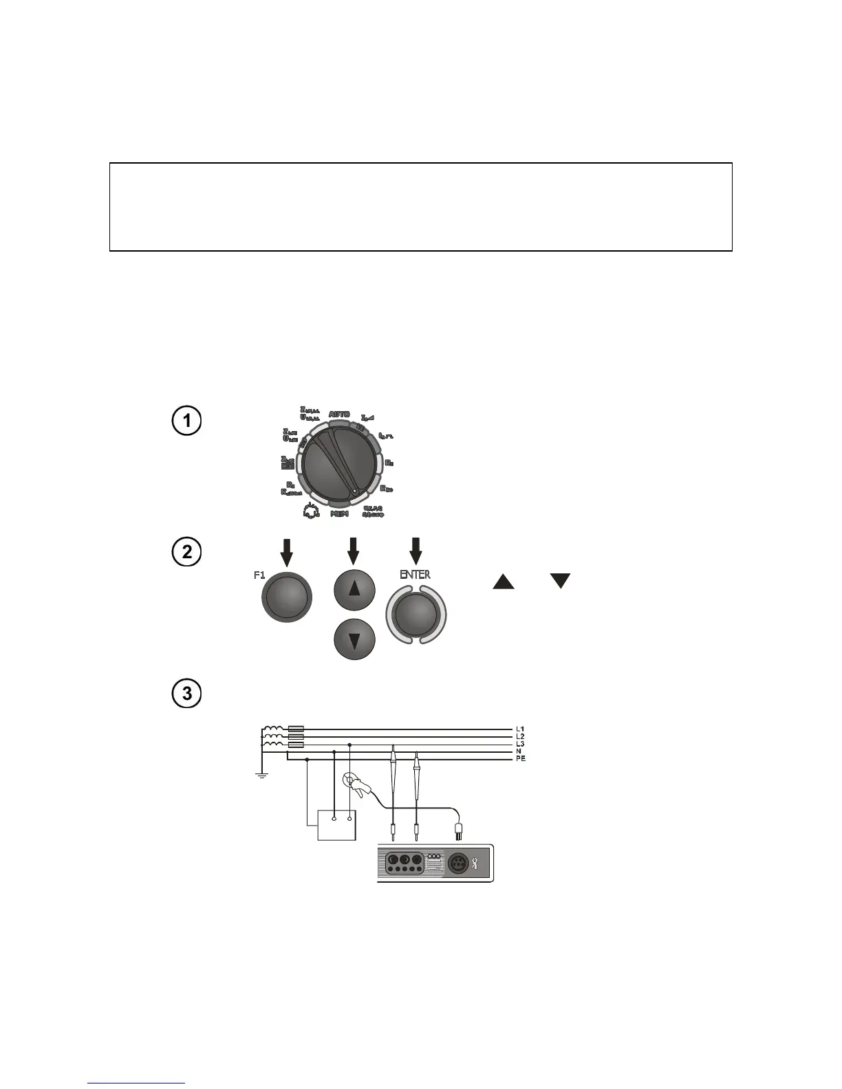
Set the rotary switch of function se-
lection at U,I,P,Q,S,f,cosφ position.
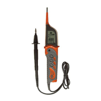
Press F1 push-button. Select
“U,I,f,cos,P,Q,S” by means
of and push-buttons
and press ENTER push-
button. (If you want to meas-
ure voltage or current only,
select a proper position.)
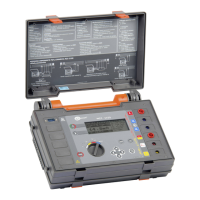
Assemble the system according to the below drawing.