5–33
2-2. TAPE PATH ADJUSTMENT
1. Preparations for Adjustment
1) Clean the tape running side (tape guide, capstan shaft, pinch
roller).
2) Connect the adjusting remote commander to the LANC terminal.
3) Turn on the HOLD switch of the adjusting remote commander.
4) Select page: 3, address: 3C, and set data: 07.
5) Connect the oscilloscope.
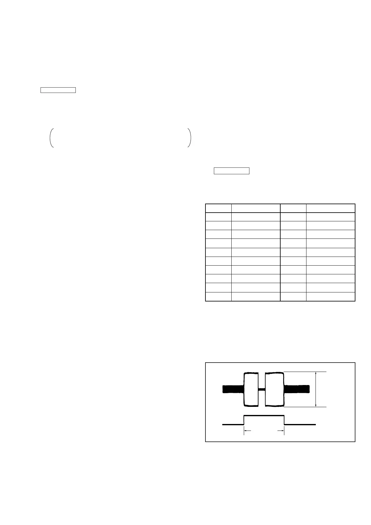
Channel 1: RJ-74 board, CN9902 Pin 8 (Note 1)
External trigger: RJ-74 board, CN9902 Pin 6
(Connect the oscilloscope via CPC-8 jig (J-6082-388-A).)
6) Playback an alignment tape (XH2-1) for tracking.
7) Check that the oscilloscope RF waveform is flat at the entrance
and exit.
If not flat, adjust according to the separate volume
“DV MECHANICAL ADJUSTMENT MANUAL I
D Mechanism ”.
8) After completing the adjustment, perform “2. Procedure after
checking operations”.
Note 1: Connect Pins 8 and 7 (GND) of CN9902 with a 75 Ω
resistor.
Table 5-2-1.
2. Procedure after operation
1) Connect the adjusting remote commander, and turn on the HOLD
switch.
2) Select page: 3, address: 3C, and set data: 00.
3) Disconnect the power of the unit.
5-2. MECHANISM SECTION ADJUSTMENTS
Mechanism Section Adjustments
For details of mechanism section adjustments, checks,
and replacement of mechanism parts, refer to the separate
volume “DV MECHANICAL ADJUSTMENT MANUAL I
D Mechanism ”.
2-1. OPERATING WITHOUT CASSETTE
1) Refer to “2. Removal” and supply the power with the cabinet
(L) assembly removed.
However, the cabinet (L) assembly incorporates the CC
DOWN switch and LANC terminal, so connect the cabinet
(L) assembly to CB-58 board electricaly.
2) Connect the adjusting remote commander to the LANC terminal.
3) Turn on the HOLD switch of the adjusting remote commander.
4) Close the cassette compartment without the cassette to set the
loading completed state.
5) Set data: 01 to page: 0, address: 01.
6) Set data: FD to page: C, address: 52, and press the PAUSE button
of the adjusting remote commander.
7) Set data: 10 to page: D, address: 10, and press the PAUSE button
of the adjusting remote commander.
8) Turn off the HOLD switch of the adjusting remote commander.
9) While pressing the CC DOWN switch, turn the power off and
then on.
The above procedure enables the mechanism to operate without the
cassette. After checking operations, be sure to perform “Procedure
After Checking Operations”.
To use the “No-Cassette Operations Mode” and “Forced Power ON
Mode” together, set the following data to page: D, address: 10.
Forced VTR power ON mode ............................................... 12
[Procedure after checking operations]
1) Set data: 01 to page: 0, address: 01.
2) Set data: FF to page: C, address: 52, and press the PAUSE button
of the adjusting remote commander.
3) Set data: 00 to page: D, address: 10, and press the PAUSE button
of the adjusting remote commander.
4) Set data: 00 to page: 0, address: 01.
5) Disconnect the power supply of the unit.
2
4
6
8
10
12
14
16
18
20
TCK
TDI
TRACK ID
GND
VCC2
VCC1
LOCK
ENV OUT
TDO8
FLTD
1
3
5
7
9
11
13
15
17
19
Signal Name Pin No. Signal Name
TMS
GND
JSWP
RF MONITOR
AGC IN
EQ IN
REF OUT
GND
C1ERP
GND
Pin No.
CH1
Must be flat
CH2
(Trigger)
3.3 msec
Fig. 5-2-1.


 To Next Page