2-1
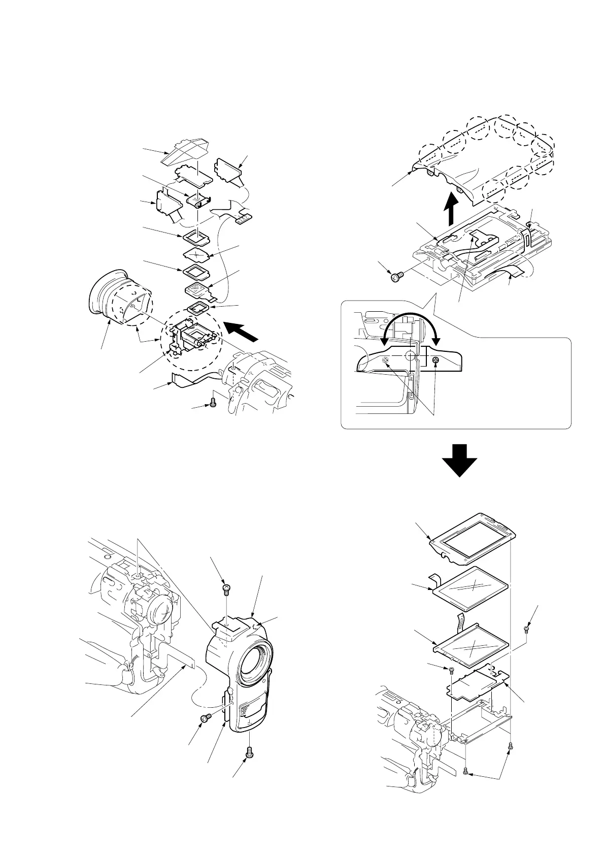
2-1. REMOVAL OF VF-115 BOARD
2-2. REMOVAL OF F PANEL ASSEMBLY
2-3. REMOVAL OF PD-85 BOARD
1 Screw
(Lock ace M2)
Claws
!¡ LCX005BK-4
(LCD902)
5 FP-535 flexible board
(CN7001 18P)
2 P cabinet (C) assembly
(Take note of nine claws.)
1 Two screws (Lock ace M2)
5 VF insulating
7 Fruorescent tube
(0.55 inch)(ND4801)
6 VF-115 board
9 BL illuminator
8 LCD cushion (3)
0 LCD cushion (3)
!™ LCD cushion (1)
2 EVF cabinet
(Rear) assembly
4 Lens holder assembly
3 FP-536 flexible board
(CN4401 27P)
CN4401
PD-85 board
1 Two screws
(Lock ace M2)
5 Flexible board
(CN5701 26P)
3 FP-541 flexible board
(CN5950 24P)
4 Flexible board
(CN5901 10P)
3 Screw (Lock ace M2)
4 F panel assembly
Claw
1 Screw (Lock ace M2)
MA-301 board
2 Screw (Lock ace M2)
2 P cabinet (M) assembly
3 Fluorescent cold
cathode tube
(ND901)
4 Liquid crystal indicator
module (LCD901)
5 Screw (Lock ace M2)
6 Screw
(Lock ace M2)
7 PD-85 board
1 Four tapping screws (B2)
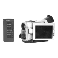
DCR-TRV7/TRV7E
NOTE: Turn the part of LCD to re-
move two screws 1 as shown
in the figure.
SECTION 2
DISASSEMBLY


 To Next Page