5–1
J-1
J-2
J-3
J-4
J-5
J-6
J-7
J-8
J-9
J-10
J-11
J-12
Filter for color temperature correction
(C14)
ND filter 1.0
ND filter 0.3
Pattern box PTB-450
Color chart for pattern box
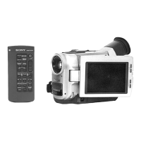
Adjusting remote commander
(RM-95-remodeled partly)
Note 1
Siemens star
Clear chart for patte2rn box
CPC-8 jig
Extension cable
(40P, 0.5 mm—39P, 0.3 mm)
Extension cable (28P, 0.8 mm)
Extension cable (80P, 0.5 mm)
IR receiver jig
SECTION 5
ADJUSTMENTS
5-1. CAMERA SECTION ADJUSTMENTS
When performing adjustments, refer to the layout
diagrams for adjustment related parts beginning from
page 5-30.
1-1. PREPARATIONS BEFORE ADJUSTMENT
(CAMERA SECTION)
1-1-1. List of Service Tools
Note:
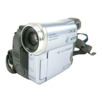
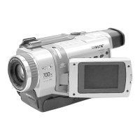
NTSC model : DCR-TRV7
PAL model : DCR-TRV7E
DCR-TRV7/TRV7E
• Oscilloscope • Regulated power supply • Color monitor
• Vectorscope • Digital voltmeter
Name Parts Code UsageRef No.
J-6080-058-A
J-6080-808-A
J-6080-818-A
J-6082-200-A
J-6020-250-A
J-6082-053-B
J-6080-875-A
J-6080-621-A
J-6082-388-A
J-6082-387-A
J-6082-385-A
J-6082-386-A
J-6082-383-A
Auto white balance adjustment/check
White balance adjustment/check
White balance check
White balance check
For checking the flange back
For adjusting the video section
For adjusting the viewfinder and LCD
For extension between the DD-96 board (CN3901) and the
CB-58 board (CN9925)
For extension between the DD-96 board (CN3902) and the
RJ-74 board (CN9903)
For extension between the RJ-74 board (CN9901) and the
CB-58 board (CN9921)
For adjusting the IR transmitter
Note 1: If the micro processor IC in the adjusting remote commander is not the new micro processor (UPD7503G-C56-12), the pages cannot
be switched. In this case, replace with the new micro processor (8-759-148-35).


 To Next Page