2-5
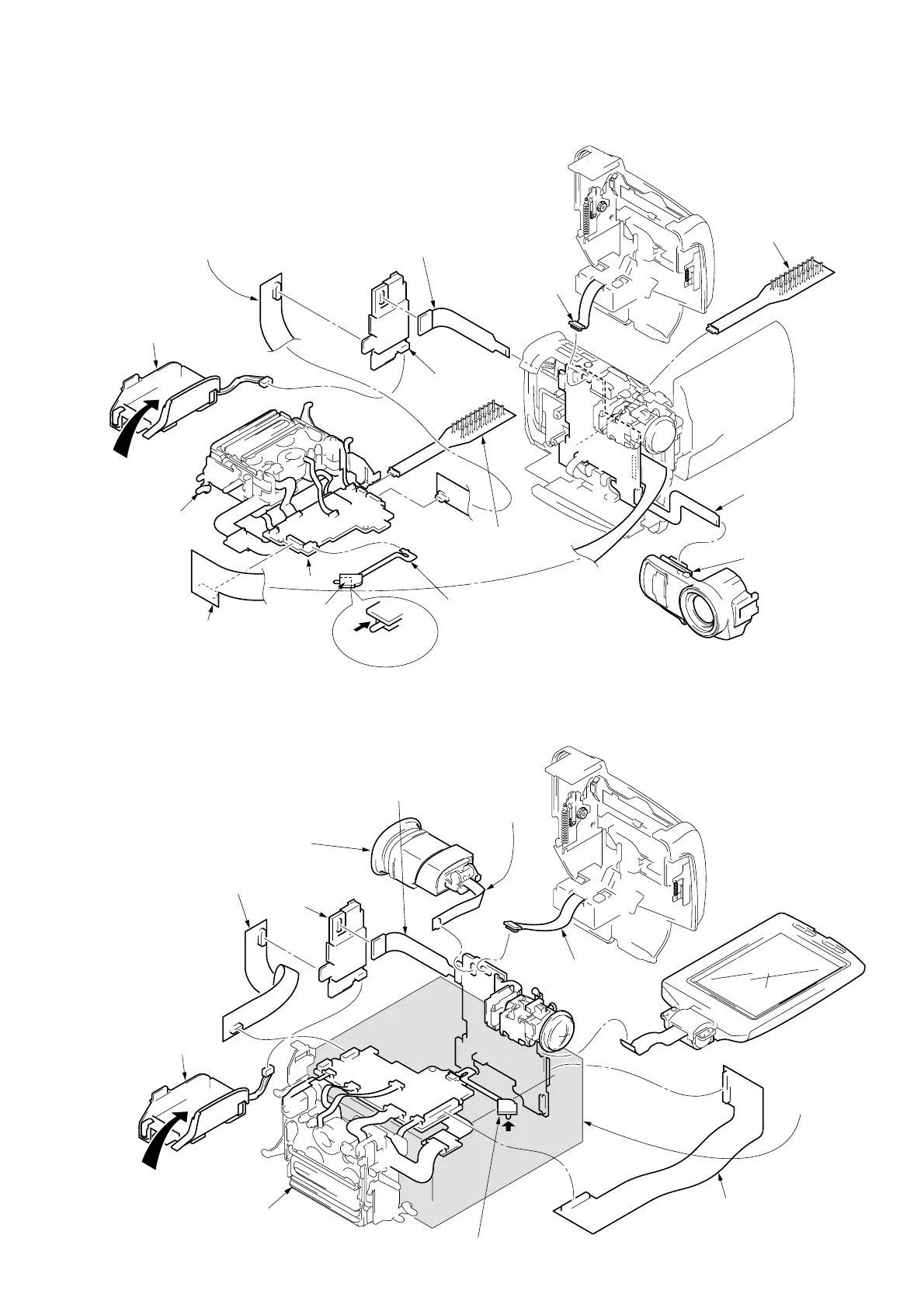
2-12. SERVICE POSITION (ELECTRICAL ADJUSTMENT OR MEASURING VOLTAGE-1)
2-13. SERVICE POSITION (MEASURING VOLTAGE-2)
Extension cord (80P 0.5mm): J-6082-386-A
(RJ-74 board (CN9901) - CB-58 board (CN9921))
Extension cord (28P 0.8mm):J-6082-385-A
(DD-96 board (CN3902) - RJ-74 board (CN9903))
F panel assembly
Battery holder assembly
(DD-96 board (CN3900))
FP-537 flexible board
(RJ-74 board (CN3105))
DD-96 board
Cabinet (L) assembly
PREPARATION: Refer to the previous section “DISASSEMBLY”, and
connect as shown in the figure after each parts has
been removed.
NOTE:The voltage measure-
ment of MA-301 board
must be performed by
removing two screws
and using a board.
Put with a tape
to turn ON.
S881
Extension cord (40P 0.5mm - 39P 0.3mm)
: J-6082-387-A
(DD-96 board (CN3901) - CB-58 board (CN9925))
FP-544 flexible board
(CB-58 board (CN9926))
Insert the battery pack.
Mechanis deck
RJ-74 board
Eject switch
CPC-8 jig: J-6082-388-A
(For EVF and LCD section adjust-
ments.)
(CB-58 board (CN9928))
LCD section
CB-58
board
FP-535 flexible board
(MA-301 board (CN7001))
PREPARATION: Refer to the previous section “DISASSEMBLY”, and
connect as shown in the figure after each parts has
been removed.
Cabinet (L) assembly
FP-536 flexible board
(CB-58 board (CN9924))
CPC-8 jig: J-6082-388-A
(For Video section adjustment.)
(RJ-74 board (CN9902))
NOTE:Refer to “2-12.”, turn ON the Eject switch (S881).
FP-537 flexible board (RJ-74 board (CN3105))
Extension cord (80P 0.5mm): J-6082-386-A
(RJ-74 board (CN9901) - CB-58 board (CN9921))
Hold up the lens and CB-
58 board with a box.
LCD section
NOTE:Refer to “2-3. Removal of PD-
85 board” for the voltage mea-
surement of PD-85 board, and
each parts must be removed.
Extension cord (40P 0.5mm - 39P 0.3mm)
: J-6082-387-A
(DD-96 board (CN3901) - CB-58 board (CN9925))
NOTE: Refer to “2-1. Removal of VF-
115 board” for the voltage mea-
surement of VF-115 board, and
each parts must be removed.
Extension cord (28P 0.8mm): J-6082-385-A
(DD-96 board (CN3902) - RJ-74 board (CN9903))
DD-96
board
Battery holder assembly
(DD-96 board (CN3900))
Insert the battery pack.
Mechanism deck
RJ-74 board
CB-58 board
FP-544 flexible board
(CB-58 board (CN9926))


 To Next Page