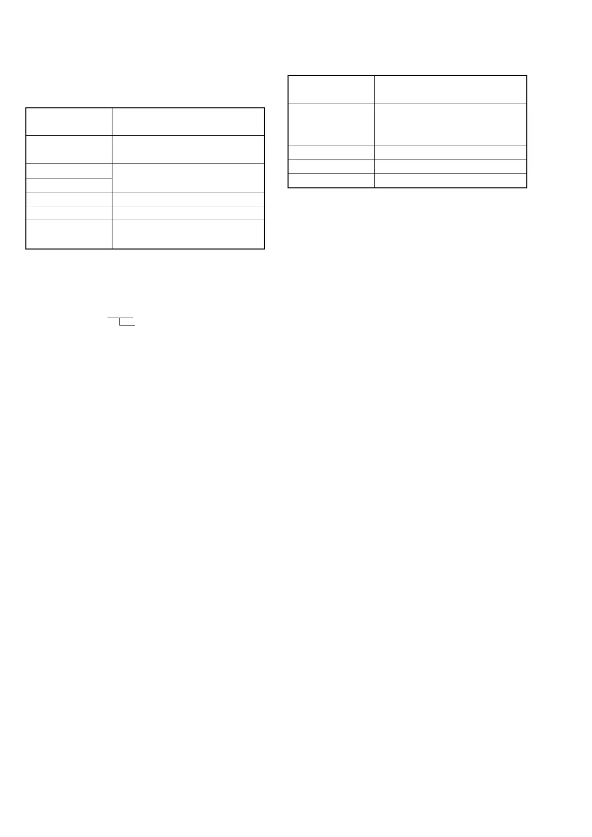
5–18
Subject
Filter
Measurement Point
Measuring Instrument
Adjustment Page
Adjustment Address
Specified Value
Clear chart
(Color bar standard picture frame)
Filter C14 for color temperature
correction
DDS display of EVF, LCD or TV monitor
(Note 1)
F
34, 35
R ratio: 2C40 to 2CC0
B ratio: 6040 to 60C0
14. Auto White Balance Adjustment
Adjust to the proper auto white balance output data.
If it is not correct, auto white balance and color reproducibility will
be poor.
Note 1: Perform “Auto White Balance Standard Data Input” before
this adjustment.
Note 2: The right four digits of the display data at the right bottom
side of the EVF, LCD and the TV monitor is the object
data.
CA 00 XXXX
Object data
Adjusting method:
1) Place the C14 filter for color temperature correction on the lens.
2) Set data: 01 to page: 0, address: 01.
3) Set data: 02 to page: D, address: 11, and press the PAUSE button
of the adjusting remote commander.
4) Set data: 01 to page: 6, address: 00.
5) Set data: 3F to page: 6, address: 01, and press the PAUSE button
of the adjusting remote commander.
6) Set data: 04 to page: 6, address: 04.
7) Change the data of page: F, address: 34, and adjust the average
value of the DDS display data (the display data at the bottom
right of the LCD, EVF or the TV monitor) to the R ratio specified
value.
8) Press the PAUSE button of the adjusting remote commander.
9) Set data: 05 to page: 6, address: 04.
10) Change the data of page: F, address: 35, and adjust the average
value of the DDS display data to the B ratio specified value.
11) Press the PAUSE button of the adjusting remote commander.
Processing after Completing Adjustments
1) Set data: 00 to page: D, address: 11, and press the PAUSE button
of the adjusting remote commander.
2) Set data: 00 to page: 6, address: 01, and press the PAUSE button
of the adjusting remote commander.
3) Set data: 00 to page: 6, address: 04.
4) Set data: 00 to page: 6, address: 00.
5) Set data: 00 to page: 1, address: 00.
>
15. White Balance Check
Checking method:
1) Check that the lens is not covered with either filter.
2) Set data: 0F to page: 6, address: 01, and press the PAUSE button
of the adjusting remote commander.
3) Check that the center of the white luminance point is within the
circle shown in Fig. 5-1-11.A.
4) Set data: 00 to page: 6, address: 01, and press the PAUSE button
of the adjusting remote commander.
5) Set data: 23 to page: 6, address: 01, and press the PAUSE button
of the adjusting remote commander.
6) Place the C14 filter on the lens.
7) Check that the center of the white luminance point settles in the
circle shown in Fig. 5-1-11. B.
8) Remove the C14 filter, and place the ND filter 1.3 (1.0 + 0.3) on
the lens.
9) Check that the white luminance point stopped moving, and then
remove the ND filter 1.3.
10) Check that the center of the white luminance point settles in the
circle shown in Fig. 5-1-11. C.
Processing after Completing Adjustments
1) Set data: 00 to page: 6, address: 01, and press the PAUSE button
of the adjusting remote commander.
Subject
Filter
Measurement Point
Measuring Instrument
Specified Value
Clear chart
(Color bar standard picture frame)
Filter C14 for color temperature
correction
ND filter 1.0 and 0.3
AUDIO VIDEO OUT terminal
Vectorscope
Fig. 5-1-11. A to C


 To Next Page