5–5
2. Order of Adjustments
Basically carry out adjustments in the order given.
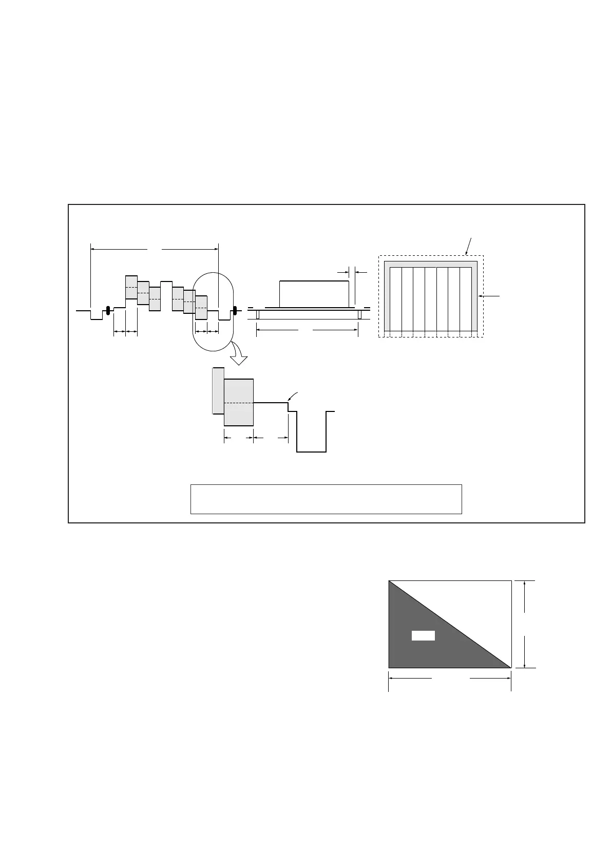
Fig. 5-1-4.
3. Subjects
1) Color bar chart (Standard image frame)
When performing adjustments using the color bar chart, adjust
the image frame as shown in Fig. 5-1-4. (Standard image frame)
2) Clear chart (Standard image frame)
Remove the color bar chart from the pattern box and insert a
clear chart in its place. (Do not perform zoom operations during
this time.)
3) Flange back adjustment chart
Make the chart shown in Fig. 5-1-5 using A0 size (1189mm x
841 mm) black and white vellum paper.
Black
White
841 mm
1189 mm
1-1-3. Precautions
1. Setting the Switches
Unless otherwise specified, set the switches as follows and perform
adjustments without loading the cassette.
1. Camera/VTR (or Player) Power Switch (PS4810 block)
.......................................................................................Camera
2. Demo mode (Menu Screen) .................................................. Off
3. Display (Menu Screen) .......................................... V-OUT/LCD
4. Digital Zoom (Menu Screen) ................................................ Off
5. STEADY SHOT Switch (Menu Screen) ...............................Off
6. Focus Switch (FC-62 board) .......................................... Manual
7. Auto lock Switch (CK4810 block) ............................ On(Green)
8. Picture effect button (CK4810 block) ...................................Off
9. 16 : 9 WIDE Switch (Menu Screen)...................................... Off
10.Back light button (TS-1 board).............................................. Off
Color bar chart standard picture frame
H
Cyan
Green
White
Magenta
Red
Blue
A B A=B
0 ± 0.1 msec
V
Enlargement
Difference in level
Electronic beam
scanning frame
Fig. b. (TV monitor picture)
Yellow
Adjust the camera zoom and direction to obtain the output waveform
shown in Fig. a and the TV monitor display shown in Fig. b.
Fig. 5-1-5.
Note: Use matte vellum paper bigger than A0, and make sure the
edges of the black and white paper joined together are not
rough.
BA
Fig. a. (Video output terminal
output waveform)
Yellow
Cyan
Green
White
Magenta
Red
Blue
CRT picture frame
B
A


 To Next Page