5–3
1-1-2. Preparations
Note 1: For details of how to remove the cabinet and boards, refer
to “2. Removal”.
Note 2: When performing only the adjustments, the lens block and
boards need not be disassembled. (except for the GUM PLL
adjustment and the original oscillation adjustmet)
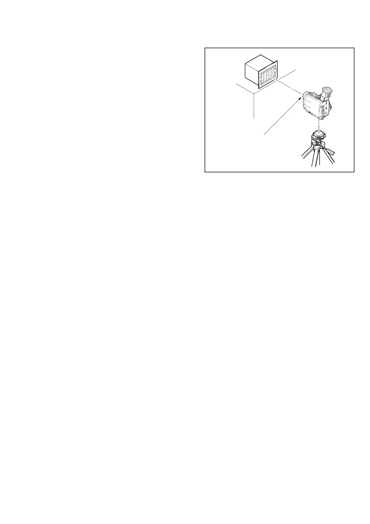
1) Connect the equipment for adjustments according to Fig. 5-1-3.
2) The front panel block (MA-301 board) need not be assembled.
If removing it, remove the following connector.
1. MA-301 board CN7001 (18P, 0.5 mm)
Note 3: As removing the cabinet (L) (CB-58 board CN9926) means
removing the lithium 3V power supply, data such as date,
time, user-set menus will be lost. After compleating
operations, reset these data. If the cabinet (L) has been
removed, the self-diagnosis data, data on history of use (total
drum rotation time) will be lost. Before removing, note
down the self-diagnosis data and data of page: 2, address:
35 to 37. (Refer to the “Service Mode” for the data on the
history of use.)
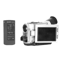
Note 4: Setting the “Forced Camera Power ON” Mode
1) Set data: 01 to page: 0, address: 01.
2) Set data: 01 to page: D, address: 10, and press the PAUSE
button of the remote commander.
The above procedure will enable the camera power to be
turned on with the cabinet (L) removed. After completing
operations, be sure to exit the “Forced Camera Power ON”
mode.
Note 5: Exiting the “Forced Camera Power ON” Mode
1) Set data: 01 to page: 0, address: 01.
2) Set data: 00 to page: D, address: 10, and press the PAUSE
button of the remote commander.
3) Set data: 00 to page: 0, address: 01.
Fig. 5-1-2.
Front of the lens
1.5m
Pattern box


 To Next Page