5–20
1-3. COLOR ELECTRONIC VIEWFINDER SYSTEM ADJUSTMENTS
Note 1: The back light (fluorescent tube) is driven by a high voltage
AC power supply. Therefore, do not touch the back light
holder to avoid electrical shock.
Note 2: When replacing the LCD unit, be careful to prevent damages
caused by static electricity.
Note 3: Set the VF PW-SAVE (Menu display) to “OFF” position,
unless specified otherwise.
Note 4: Set the VF BRIGHT (Menu display) to the center.
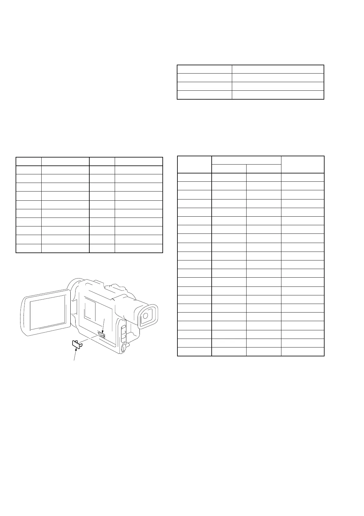
[Adjusting connector]
Most of the measuring points for adjusting the view-finder are
concentrated in CN9928 of the CB-58 board.
Connect the measuring instruments via the CPC-8 jig (J-6082-388-
A).
The following table shows the Pin No. and signal name of CN9928.
Adjusting method:
1) Set data: 01 to page: 0, address: 01.
2) Select page: D, and input the data in the following table.
Note: To write in the non-volatile memory (EEPROM), press
the PAUSE button of the adjusting remote commander
each time to set the data.
3) Set data: 00 to page: 0, address: 01.
1. EVF Initial Data Input
Camera
Arbitrary
D
70 to 7A, 87 to 8F, 99
Mode
Subject
Adjustment Page
Adjustment Address
DEC FSC
GND
DEC R-Y
DEC B-Y
AFC ERR
I1 Y AD
I1 CR AD
I1 CB AD
I1 CR/CB AD
N. C.
VG
GND
HST
GND
XHCG
VCO
UNREG —
UNREG +
GND
EVF VG
2
4
6
8
10
12
14
16
18
20
Signal NamePin No.Signal NamePin No.
1
3
5
7
9
11
13
15
17
19
Table 5-1-2.
Remove the cover
CN9928
[Power Supply Voltage]
Adjust the power supply voltage so that the voltage of Pin !∞ of
CN9928 on CB-58 board becomes 8.4 ± 0.1 Vdc .
Fixed value
Fixed value
Fixed value
Fixed value
Fixed value
Fixed value
Fixed value
Fixed value
Fixed value
Fixed value
Fixed value
Fixed value
Fixed value
Fixed value
70
60
A1
80
80
70
90
5A
70
74
B0
E3
38
00
20
20
02
00
12
40
31
70
60
A1
80
80
70
90
5A
70
79
B0
85
38
00
20
20
02
00
12
40
31
70
71
72
73
74
75
76
77
78
79
7A
87
88
89
8A
8B
8C
8D
8E
8F
99
Remark
PALNTSC
Data
Address
Table 5-1-3.


 To Next Page