5–52
2. Recording System Check
Note1: Peform “Playback System Check” before this check.
Note2: Close the LCD panel.
1) Playback the BIST check tape.
2) Input the following data in order.
Note: Press the PAUSE button each time set the data.
Data
C6 (NTSC), F8 (PAL)
90 (NTSC), 3E (PAL)
Address
15
14
Page
4
4
20) When the IC1701(D1) n IC3501 (INDI) recording system is
normal, following data will be displayed in page: 4, address: 16
and 17.
Data
41 (NTSC), B9 (PAL)
7D (NTSC), F6 (PAL)
Address
17
16
Page
4
4
21) When the IC1901(A1) n IC1701(D1) recording system is
normal, following data will be displayed in page: 4, address: 18
and 19.
Data
76 (NTSC), CE (PAL)
B9 (NTSC), E7 (PAL)
Address
19
18
Page
4
4
22) When the IC1701(D1) n IC6101(DX) recording system is
normal, following data will be displayed in page: 4, address: 1A
and 1B.
Page
4
4
Address
1B
1A
Data
72 (NTSC), 8C (PAL)
37 (NTSC), CD (PAL)
23) Set data: 56 to page: D, address: 14, only for AEP and UK
models, and press the PAUSE button.
24) Set data: (03)[01] to page: D, address: 15, and press the PAUSE
button.
( ): NTSC model, PAL E/Tourist model
[ ]: PAL AEP/UK model
25) Set data: 00 to page: 0, address: 01.
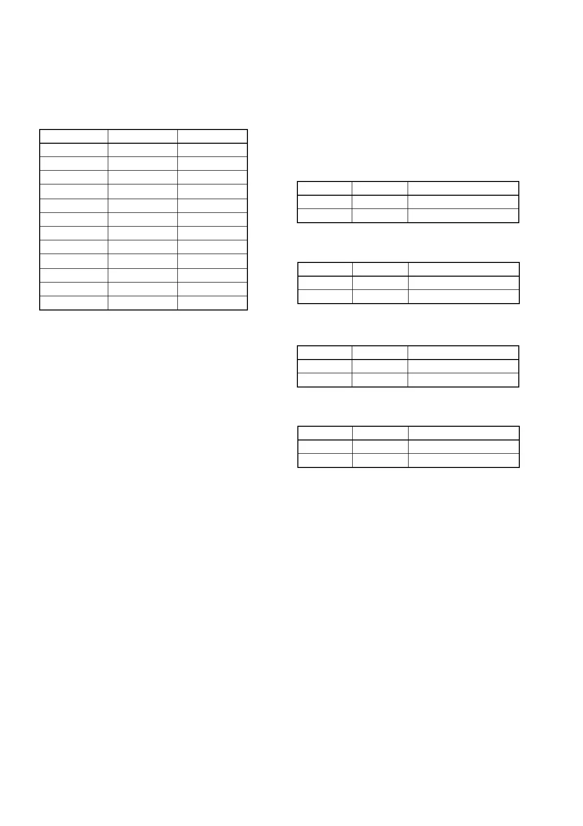
Data
01
02
01
01
0A
00
01
0E
00
01
8E
00
Address
41
0F
0E
40
0F
40
40
0F
40
40
0F
40
Page
4
4
4
4
4
4
4
4
4
4
4
4
3) Set to the stop mode.
4) While keep the HOLD switch of the adjusting remote commander
at ON (SERVICE) position, eject the BIST check tape and insert
a tape for recording in place of the tape.
5) Set data: 01 to page: 0, address: 01.
6) Set data: 57 to page: D, address: 14, only for AEP and UK
models, and press the PAUSE button.
7) Set data: (07)[05] to page: D, address: 15, and press the PAUSE
button.
( ): NTSC model, PAL E/Tourist model
[ ]: PAL AEP/UK model
8) Set the HOLD switch of the adjusting remote commander to
OFF position.
9) Press the REC button and set to the VTR recording mode.
10) Set the HOLD switch of the adjusting remote commander to ON
(SERVICE) position.
11) Set data: 02 to page: 4, address: 11 and press the PAUSE button.
12) Set data: 02 to page: 4, address: 13 and press the PAUSE button.
(The data will be automatically return to “00”.)
13) Set data: 00 to page: 4, address: 11 and press the PAUSE button.
IC1701 (D1) Recording System Check
14) Set data: 0D to page: 3, address: 01 and press the PAUSE button.
15) Set data: FF to page: 4, address: 1C and press the PAUSE button.
16) Set data: 04 to page: 4, address: 11 and press the PAUSE button.
17) Set data: 00 to page: 4, address: 11 and press the PAUSE button.
18) Set data: 03 to page: 4, address: 13 and press the PAUSE button.
(The data will be automatically return to “00”.)
19) When the IC1601 (U1) n IC1701 (D1) recording system is
normal, following data will be displayed in page: 4, address: 14
and 15.


 To Next Page