5-24
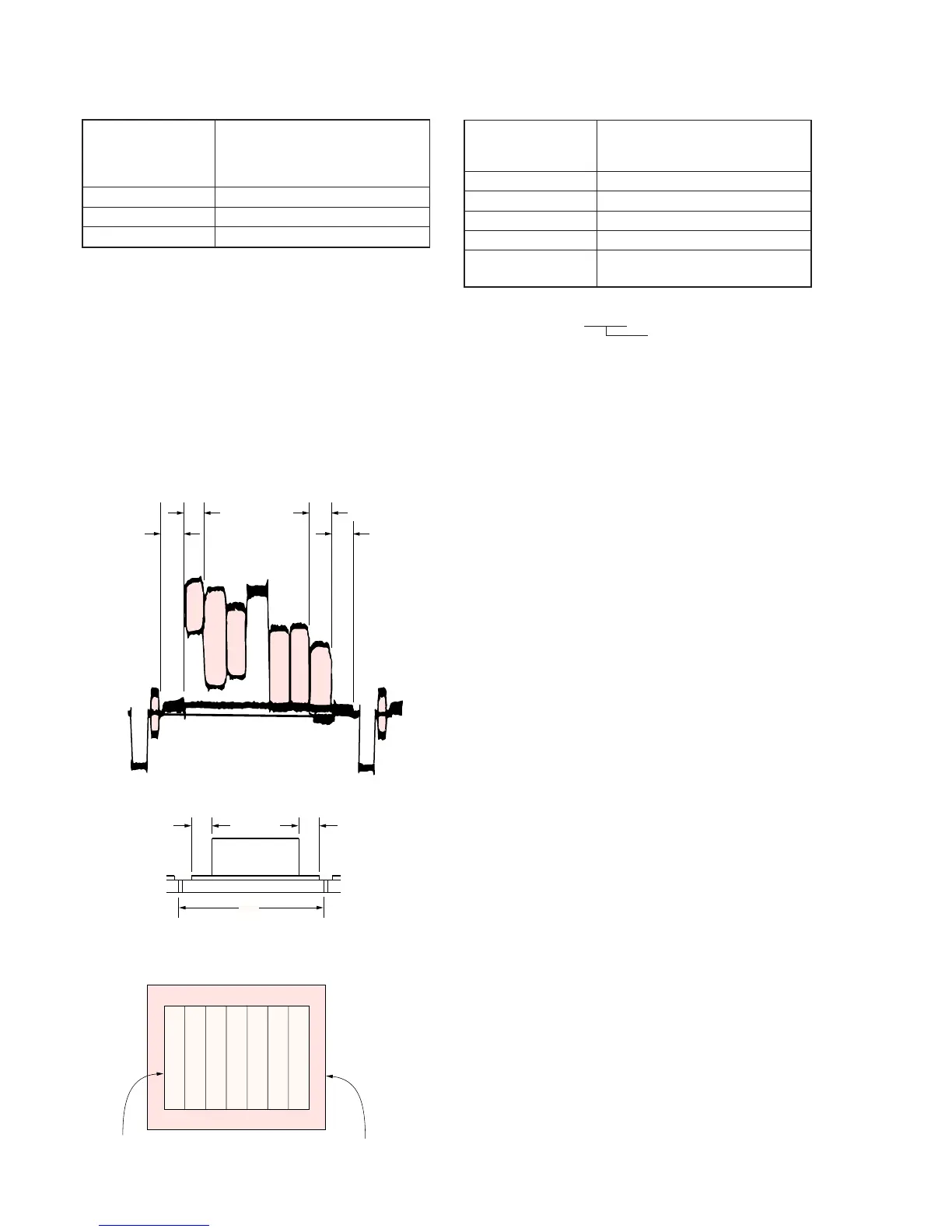
8. Picture Frame Setting
Subject Color bar chart
(Color reproduction adjustment
frame)
(1.5m from the front of the lens)
Measurement Point Video output terminal
Measuring Instrument Oscilloscope and TV monitor
Specified Value A=B, C=D, E=F
Switch setting:
1) NIGHT SHOT ..................................................................OFF
2) DIGITAL ZOOM (Menu display) ...................................OFF
Setting method:
1) Adjust the zoom and the camera direction, and set to the
specified position.
2) Mark the position of the picture frame on the monitor display,
and adjust the picture frame to this position in following
adjustments using “Color reproduction adjustment frame”.
9. AGC GAIN Calibration Adjustment
Subject Clear chart
(Color reproduction adjustment
frame)
Measurement Point Display data of page 1 (Note)
Measuring Instrument Adjustment remote commander
Adjustment Page E
Adjustment Address 3A, 3B, 3C, 3D
Specified Value Data1 : 0196 to 02D3
Data2 : 0B35 to 1669
Note: Displayed data of page 1 of the adjustment remote commander.
1 : XX : XX
Display data
Switch setting:
1) NIGHT SHOT ..................................................................OFF
Adjusting method:
1) Select page: 0, address: 01, and set data: 01.
2) Select page: 6, address: 40, and set data: 02.
3) Select page: 6, address: 41, and set data: 01.
4) Select page: 6, address: 01, set data: 71, and press the PAUSE
button of the adjustment remote commander.
(The AGC gain calibration adjustment is performed and the
adjustment data is stored in page: E, address: 3A to 3D.)
5) Select page: 6, address: 02, and check that the data is “01”.
6) Select page: 6, address: 01, set data: 00, and press the PAUSE
button.
Checking method:
1) Select page: 0, address: 01, and set data: 01.
2) Select page: F, address: 10, set data: 47, and press the PAUSE
button.
3) Select page: 6, address: 9A, and set data: 03.
4) Select page: 6, address: 01, set data: 9B, and press the PAUSE
button.
5) Select page: 6, address: 02, and check that the data is “01”.
6) Select page: 1, and check that the display data (Note) satisfies
the specified value of data1.
7) Select page: 6, address: 01, set data: 00, and press the PAUSE
button.
8) Select page: 6, address: 9A, and set data: 99.
9) Select page: 6, address: 01, set data: 9B, and press the PAUSE
button.
10) Select page: 6, address: 02, and check that the data is “01”.
11) Select page: 1, and check that the display data (Note) satisfies
the specified value of data2.
Processing after Completing Adjustments:
1) Select page: F, address: 10, set data: 00, and press the PAUSE
button.
2) Select page: 6, address: 01, and set data: 00, and press the
PAUSE button.
3) Select page: 6, address: 40, and set data: 00.
4) Select page: 6, address: 41, and set data: 00.
5) Select page: 6, address: 9A, and set data: 00.
6) Select page: 0, address: 01, and set data: 00.
A=B
C=D
A
BC
D
E=F
V
EF
Color bar chart picture frame
Monitor TV picture fram


 To Next Page