2-1
DCR-TRV8/TRV8E/TRV10/TRV10E
SECTION 2
DISASSEMBLY
NOTE: Follow the disassembly procedure in the numerical order given.
The following flow chart shows the disassembly procedure.
DCR-TRV8/8E/10/10E
2-1. LCD panel (PD-110 board, invertor trans unit)
2-2. Front panel assembly
2-3. Cabinet (L), BT panel assembly 2-11. CK-84 board, Speaker
2-12. LCD, Control swith block2-4.EVF
2-5.LB-60 board2-6. DD-123 board, VC-217 board
2-7. Mechanism deck
2-8. CS flame assembly
2-9.Lens, Outer connector (hot shoe), JK-170 board
2-10.MS shassis, Control switch block (PS-4550)
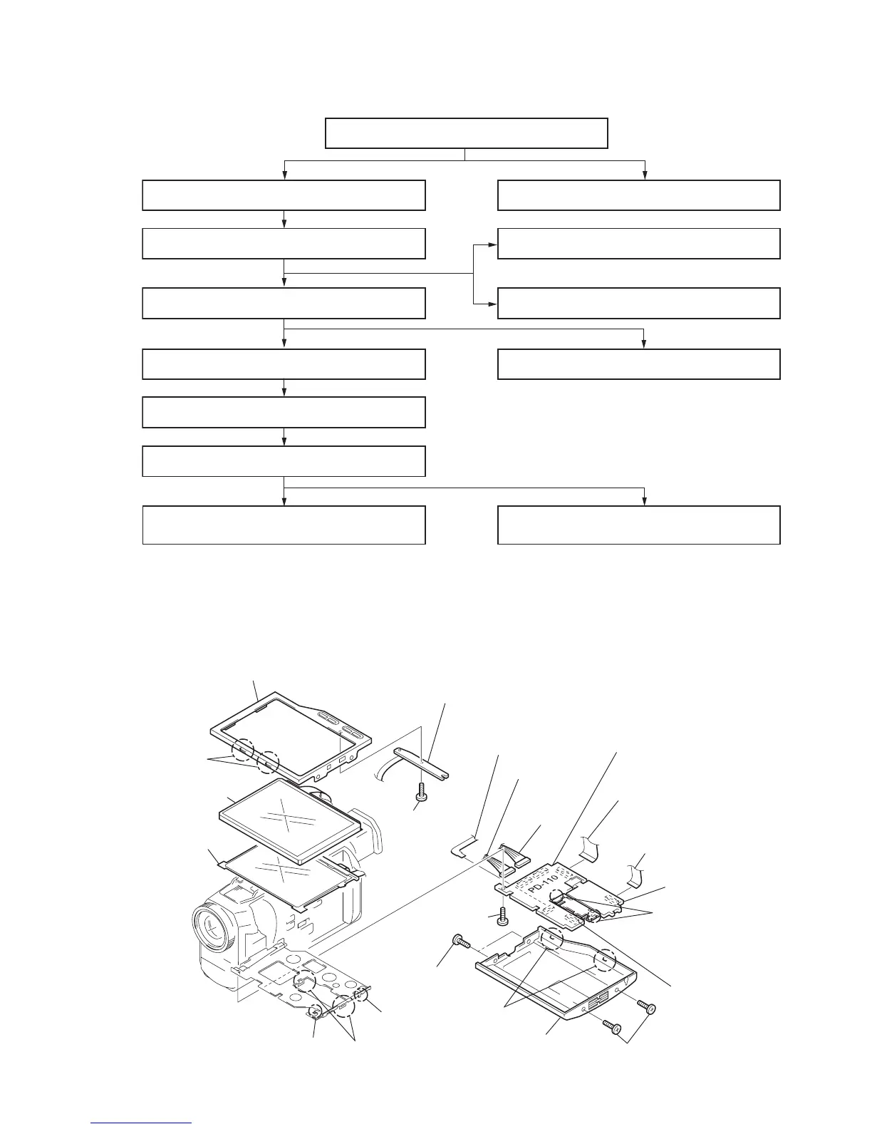
2-1. LCD PANEL (PD-110 BOARD, INVERTOR TRANS UNIT)
1
Two screws (M1.7) lock ace
2
Two screws
(M1.7) lock ace
3
P cabinet (M) assembly
(Remove the four claws
A
and
B
.)
5
FP-90 flexible board
CN8613 6P (PD-110 board)
!•
FP-90 flexible board
!¶
Tapping screw
(M1.7
×
3.5)
!™
Screw
(M1.7
×
2.5)
!£
PD-110 board
(Remove the two claws
D
and
E
.)
8
Indication LCD block
assembly (LCD901)
9
Cold cathode
fluorescent tube
(ND901)
!§
Inverter transformer uni