5-43
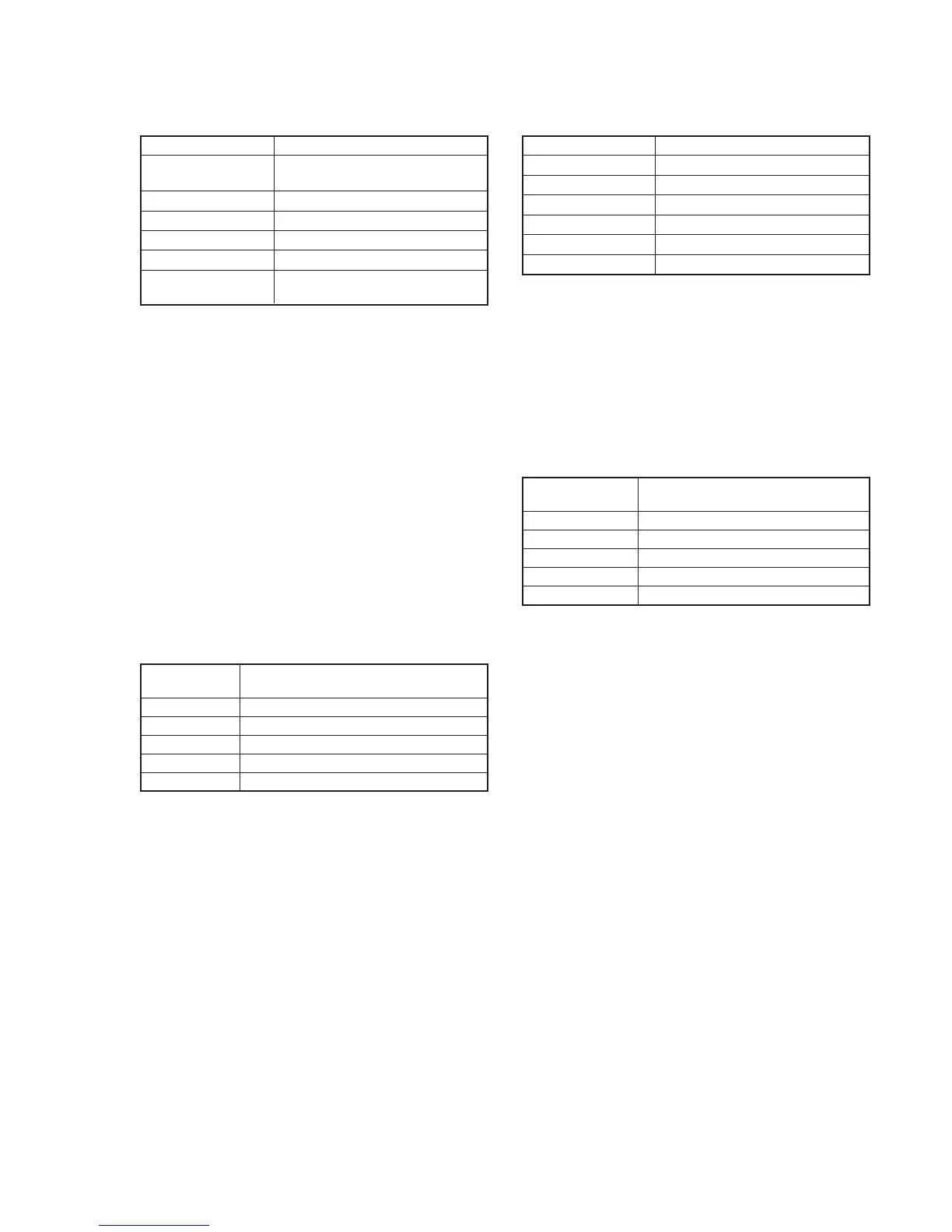
5-3. APC & AEQ Adjustment (VC-217 board)
Mode Playback
Signal Recorded signal at “Preparations
before adjustments”
Measurement Point Pin @º of CN2904 (RF MON) (Note 1)
Measuring Instrument Oscilloscope
Adjustment Page C
Adjustment Address 18, 19, 1B, 1C, 21, 73
Specified Value The display data of page: 3, address:
03 is “00”
Note 1: Connect a 75Ω resistor between Pin @º and Pin !ª (GND) of
CN2904.
75Ω resistor (Parts code: 1-247-804-11)
Note 2: The “AGC Center Level Adjustment” must have already been
completed before starting this adjustment.
Adjusting method:
1) Select page: 0, address: 01, and set data: 01.
2) Playback the recorded signal at “Preparations before
adjustments”
3) Select page: 3, address: 33, and set data: 08.
4) Check that the playback RF signal is stable.
5) Select page: 3, address: 01, set data: 07, and press the PAUSE
button of the adjustment remote commander.
6) Select page: 3, address: 02, and check that the data changes
from “07” to “00” in about 15 seconds after pressing the PAUSE
button.
7) Select page: 3, address: 03, and check that the data is “00”.
Note: If the data of page: 3, address: 03 is other than “00”, adjustment
has errors. (Take an appropriate remedial measures according
to the errors referring to the following table. )
8) Perform “Processing after Completing Adjustments”.
Note 3: If this data is displayed twice successively, the machine is defective.
5-4. Processing after Completing Adjustments
1) Select page: 2, address: 30, and set data: 00.
2) Select page: 3, address: 33, and set data: 00.
3) Select page: 0, address: 01, and set data: 00.
Data of page: 3,
address: 03
20
30
50
60
80
Contents of defect
Perform re-adjustment. (Note 3)
The machine is defective
Perform re-adjustment (Note 3)
The machine is defective
The machine is defective
6. PLL f0 & LPF f0 Final Adjustment (VC-217 board)
Mode VTR stop
Signal Arbitrary
Measurement Point Display data of page: 3, address: 03
Measuring Instrument Adjustment remote commander
Adjustment Page C
Adjustment Address 1F, 20, 22, 47
Specified Value Bit2, bit3 and bit6 are “0”
Adjusting method:
1) Select page: 0, address: 01, and set data: 01.
2) Select page: 3, address: 01, set data: 30, and press the PAUSE
button of the adjustment remote commander.
3) Select page: 3, address: 02, and check that the data changes to
“00”.
4) Select page: 3, address: 03, and check that bit2, bit3 and bit 6
of the data are “0”.
Note: If bit2, bit3 or bit 6 of the data is “1”, there are errors. (For the
error contents, see the following table. For the bit values, refer
to “5-4. SERVICE MODE”, “4-3. 3. Bit value discrimination”.)
5) Select page: 0, address: 01, and set data: 00.
Bit value of page: 3,
address: 03
bit 4 = 1
bit 5 = 1
bit 6 = 1
bit 3 = 1
bit 2 = 1
Error contents
PLL f
0
, even channel is defective
PLL f
0
, odd channel is defective
LPF f
0
is defective
PLL f
0
final adjustment is defective
PLL f
0
final adjustment time-out