EasyManua.ls Logo

Sony DCR-TRV8 - Front Panel Assembly; Cabinet (L), Bt Panel Assembly

Sony DCR-TRV8
182 pages
Print Icon
To Next Page IconTo Next Page
To Previous Page IconTo Previous Page
Loading...
2-2
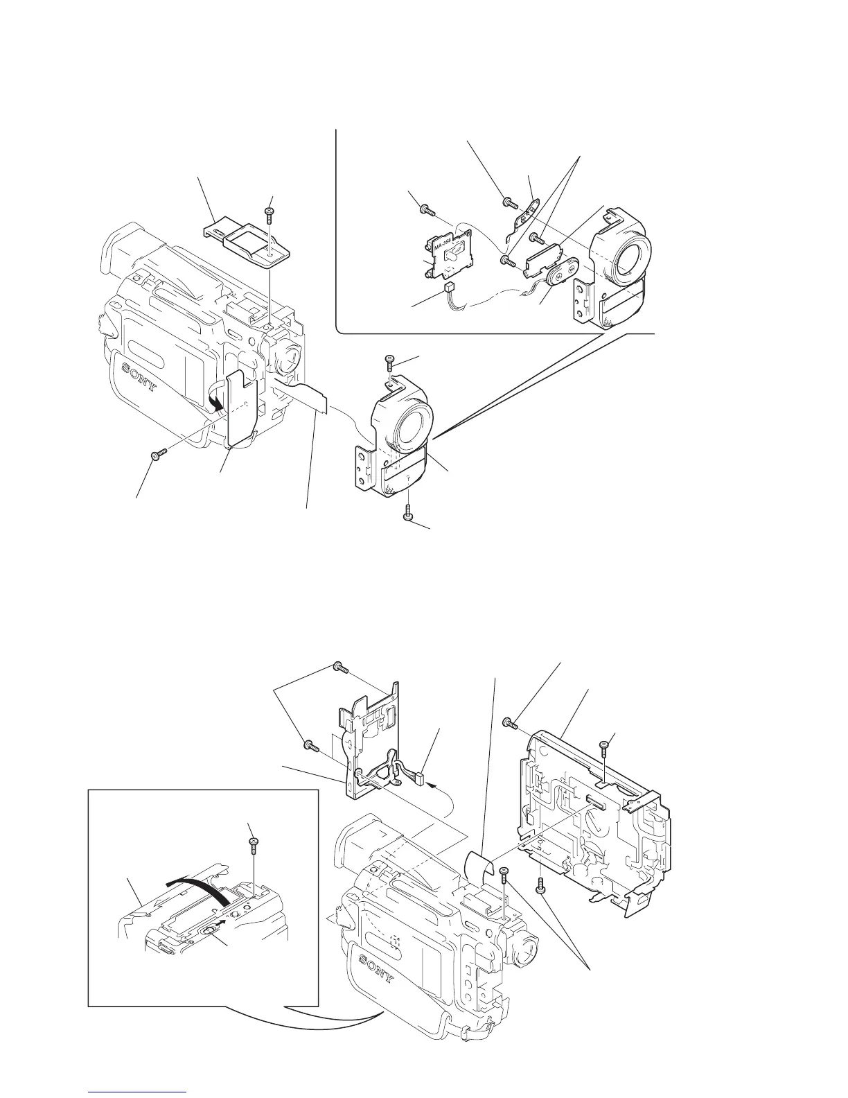
2-2. FRONT PANEL ASSEMBLY
1
Screw (M1.7) lock ace
3
Screw (M1.7) lock ace
9
Tapping screw (M1.7
×
3.5)
!£
Connector
CN7300 4P (MA-358 board)
!™
MA-358 board
!¡
Tapping screw (M1.7
×
3.5)
!¢
Two tapping screws
(M1.7
×
3.5)
!∞
Microphone retaine
r
assembly
!§
Microphone unit
7
F panel assembly
4
Screw (M1.7) lock ace
6
Screw (M1.7) lock ace
8
JK-170 board
CN7306 26P (MA-358 board)
!º
SE-94board
CN7307 5P
(MA-358 board)
2
Top cabinet assembly
5
Open the jack cover.
2-3. CABINET (L), BT PANEL ASSEMBLY
1
Screw (M1.7) lock ac
e
3
Screw (M1.7) lock ace
8
Three screws
(M1.7) lock ace
9
BT panel assembly
!º
Connector
CN8610 3P
(DD-123 board)
5
Screw (M1.7) lock ace
6
Cabinet (R) assembly
7
FP-82 flexibli board
CN8608 60P (CK-84 board)
4
Push the knob in the direction of the
arrow
A
, and open the grip cabinet
in the direction of the arrow
B
.
2
Two screws (M1.7) lock ace
Knob
Grip cabinet
A
B

Table of Contents