2-8
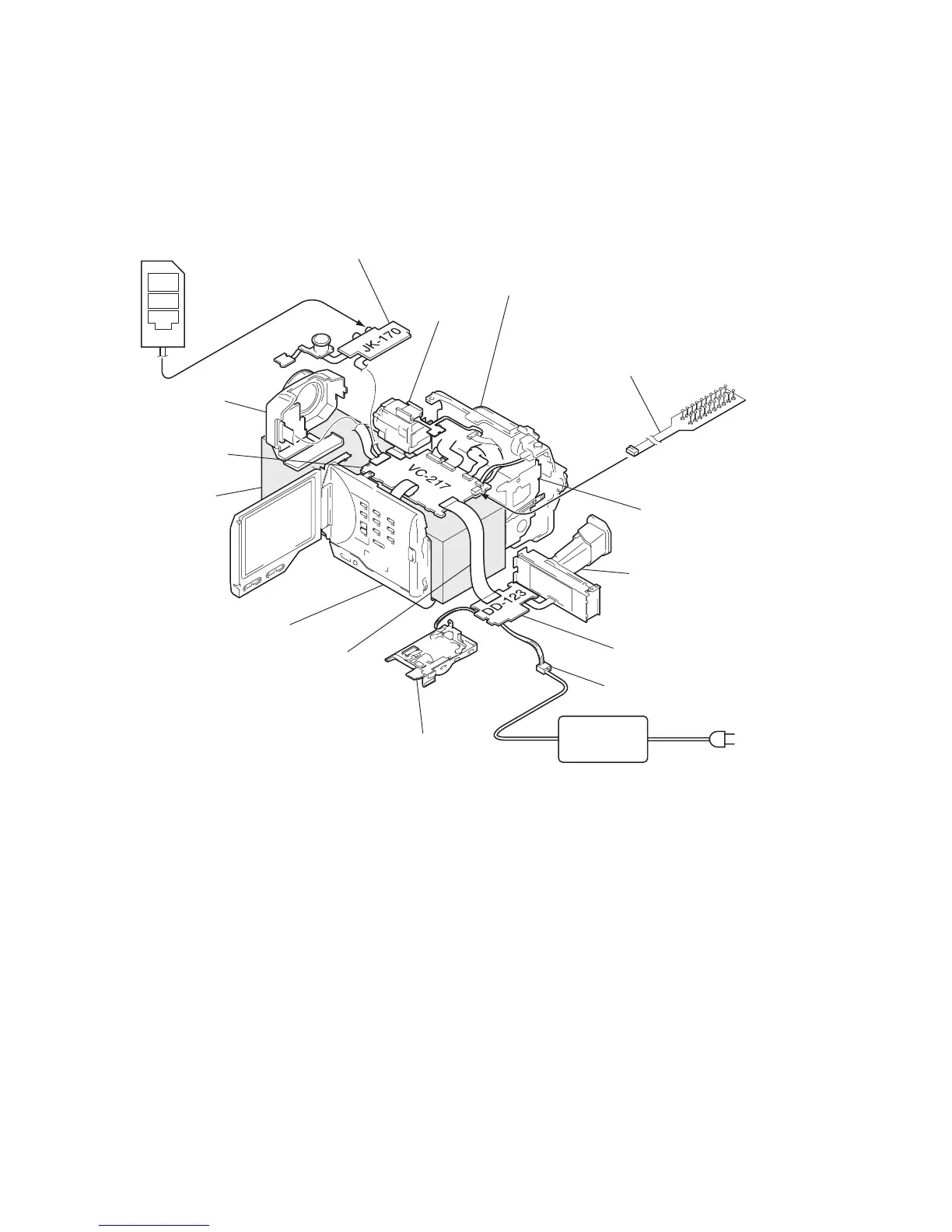
2-13.SERVICE POSITION (Mainly for voltage measurement and check)
AC IN
Adjustment remote
commander (RM-95)
AC adapter
(AC-L10 and
AC-VQ800,etc.)
CPC-8 tarminal board jig
(J-6082-388-A)
Base
JK-170 board
Lens assembly
Cabinet (L) assembly
EVF
DD-123 board
DC IN (8.4V)
BT panel assembly
Cabinet (R) assembly and LCD
Extension cable
(J-6082-395-A)
VC-217 board
F panel assembly
Mechanism deck
Firstly: Remove the respective parts by referring to "Disassembly 2-2 through 2-4, and 2-6 through 2-9".
Then, connect them as shown.
(Support the VC-217 board, lens block, and front panel assembly with a
base or the like.)
 Loading...