Chapter 2 Fitting and Connections
34
Chapter 2 Fitting and Connections
VTR selector settings on the CA-537/537P
a) Set the audio input level on the VO-6800/6800PS to –60
dB.
b) When the BVV-5/5PS is used as a portable VTR, a VA-5/
5P VTR Composite/Component Adaptor is required.
c) Set the input selector switch on the AG-7400 to Y/C.
VTR selector settings on the CA-327/327P
a) Set the audio input level on the VO-6800/6800PS to –60
dB.
b) Set the input selector switch on the AG-7400 to Y/C.
Connected VTR
VTR
selector
switch
setting
Video output
signal
Audio
output
signal
level
Sony broadcast and
professional VTRs:
BVU-150/150P and
VO-6800/6800PS
a)
1 Composite –60 dB
Sony professional
VTRs: VO-8800/
8800P and EVV-
9000/9000P
2 Y/C –60 dB
Panasonic AG-6400
VHS VTR
3 Composite –20 dB
Panasonic AG-7400 S-
VHS VTR
b)
4 Y/C –20 dB
Connections
Panasonic AG-6400
VHS VTR
Connected VTR VTR
selector
switch
setting
Video output
signal
Audio
output
signal
level
Sony broadcast and
professional VTRs:
BVU-150/150P, VO-
6800/6800PS
a)
,
BVW-50/50P and
BVV-5/5PS
b)
1 Composite
(BVU-150/
150P and VO-
6800/6800PS)
or component
(BVW-50/50P
and BVV-5/
5PS)
–60 dB
Sony professional
VTRs: VO-8800/
8800P and EVV-
9000/9000P
3 Y/C –60 dB
2 Composite –20 dB
Panasonic AG-7400 S-
VHS VTR
c)
and JVC
BR-S405 S-VHS VTR
3 Y/C
–20 dB
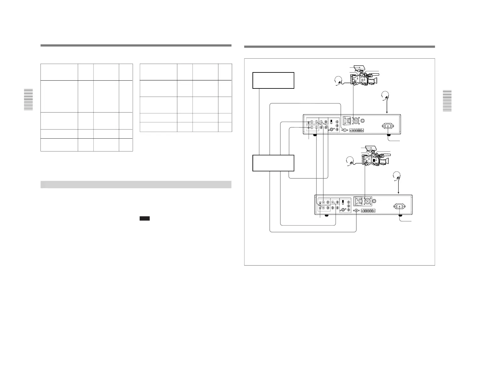
Connecting a Number of Cameras (Using a Camera Control Unit)
When using a number of cameras in the studio, it may
be necessary to use a CCU-M5/M5P/M7/M7P Camera
Control Unit to provide video and color sync between
cameras, and special effects and other devices to allow
switching, wipes and so forth.
In the studio it may also be convenient to use a DXF-
40B/40BCE/50B/50BCE Viewfinder.
The figure in the next page shows an example studio
configuration.
For details, consult your Sony dealer.
Note
With the DXC-D30/D30P, color matrix switching on
the CCU-M5/M5P is invalid.