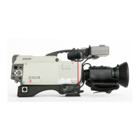
DXC-D30 (UC)
DXC-D30P (CE)
3-5
3-3. CAMERA ADJUSTMENT
nBefore the adjustment, enter the “PAGE 1” of
SERVICE menu, and perform the “RESET”.
3-3-1. Sub-Carrier Frequency Adjustment
Equipment: Frequency counter
To be extended: ES-12 board
Test point: TP501 (GND: E1(extension board))
/ES-12 board
Adjusting point: SERVICE menu “PAGE 8”
→ SC FREQ :
Adjust the sub-Carrier Frequency by UP
switch or DOWN switch.
Specification: 3,579,545 ± 10 Hz (for NTSC)
4,433,618 ± 10 Hz (for PAL)
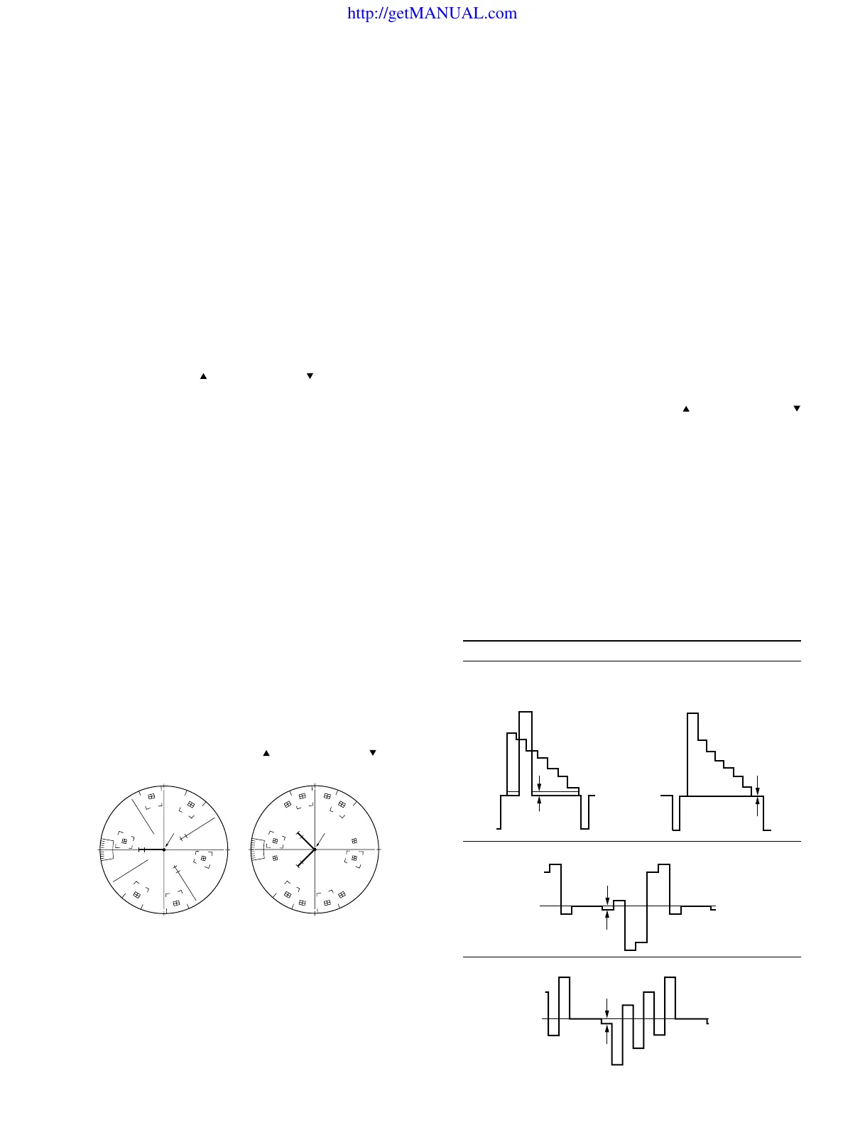
3-3-2. INT SC-H Phase Adjustment
Note:
Stated below is a procedure with the SC-H phase measuring
equipment (Tektronix Waveform monitor 1765).
If any other equipment is used, perform adjustment at the
following adjustment point by reading the instruction manual
attached.
Equipment: Waveform monitor (SC-H Phase mode)
Preparation:
• Put the Tektronix Waveform monitor 1765 to SC-H mode.
Test point: VIDEO OUTconnector/camera side
Adjustment Procedure
• SERVICE menu “PAGE 8”
→ SC-H
• Adjust the phase relationship between SC (Burst) and H
beam spot correctly by UP
switch or DOWN switch.
[for NTSC] [for PAL]
Note:
After this adjustment, set the mode of Tektronix Waveform
monitor 1765 to “WFM” mode.
R
M
G
C
Y
G
Y
L
B
R
M
G
C
Y
G
Y
L
B
B
C
(PAL)(NTSC)
A
A
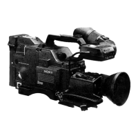
3-3-3. Y/R-Y/B-Y CLP Level Adjustment
Equipment: Oscilloscope
To be extended: IF-532 board
Preparation: OUTPUT/DL/DCC + switch/camera side
→ BARS
Trigger: HD (TP83/extension board)
Adjustment Procedure:
1. Select “PAGE 10” of SERVICE menu, make sure that
R-Y and B-Y mode must be “ON”.
2. SERVICE menu “PAGE 6”
→ Y CLP :
R-Y CLP :
B-Y CLP :
3. Adjust the following items by UP
switch or DOWN
switch.
Note: In case of Y CLP for NTSC model, perform the
adjustment as follows.
1 Select “PAGE 9” of SERVICE menu, and set
the “SETUP” to “OFF”.
2 Select “PAGE 6” of SERVICE menu, and move
the cursor to Y CLP.
3 Adjustment: A = 0 ± 5 mV
4 Select “PAGE 9” of SERVICE menu, and set
the “SETUP” to “ON”.
5 And return to “PAGE 6”.
Extension board (GND : TP63/IF-532 board)
Item Test Point Specification
Y CLP TP61 A = 0 ± 5 mV
R-Y CLP TP60 B = 0 ± 5 mV
B-Y CLP TP62 C = 0 ± 5 mV
http://getMANUAL.com