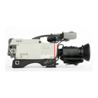
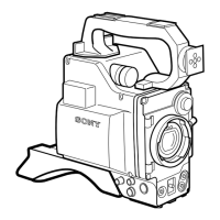
DXC-D30 (UC)
DXC-D30P (CE)
3-9
3-3-11. CCD Output Level Adjustment
Note :
• Use a reflection type with chart for this adjustment, therefore,
control the light so that the white area of chart is exactly
3200K of color temperature.
• If use the pattern box, make sure that the color temperature
must be 3200K.
• Usually, this adjustment is not required.
Only when the output level of CCD unit is large different from
the specification.
• When the new CCD unit of spare parts is replaced, this
adjustment is not required because of the correct adjustment
at the factory.
Object: Grayascale chart
Equipment: Oscilloscope
To be extended: VA-169 board
Preparation:
• OUTPUT/DL/DCC + switch/camera side → CAM
• WHITE BAL switch : PRESET
• Chart frame = Underscanned monitor frame
• Adjust the lens iris so that the video level at TP27/extension
board (VA-169 board) is 165 ± 5 mV.
Trigger: HD (TP72/extension board)
Adjustment Procedure
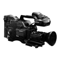
1. Test point: TP15/extension board (VA-169 board)
1RV1/PA-187 (B) board
Specification : A = 165 ± 5 mV
2. Test point: TP21/extension board (VA-169 board)
1RV1/PA-189 (R) board
Specification : A = 165 ± 5 mV
3-3-10. VF SYNC/BLKG Level Adjustment
Equipment: Oscilloscope
To be extended: ES-12 board
Preparation: OUTPUT/DL/DCC + switch/camera side
→ BARS
Trigger: HD (TP84/extension board)
Adjustment Procedure
1. SERVICE menu “PAGE 7”
VF SYNC
→ VF BLKG
Note: For the adjustment procedure, at the first “VF
BLKG” adjustment is done, and next, “VF SYNC”
adjustment is done.
2. Adjust the following items by UP
switch or DOWN
switch.
Extension board (GND : TP81/ES-12 board)
Item Test Point Specification
VF BLKG TP82 NTSC : A = 50 ± 10 mV
PAL : A = 50 ± 10 mV
VF SYNC TP82 NTSC : B = 286 ± 10 mV
PAL : B = 300 ± 10 mV
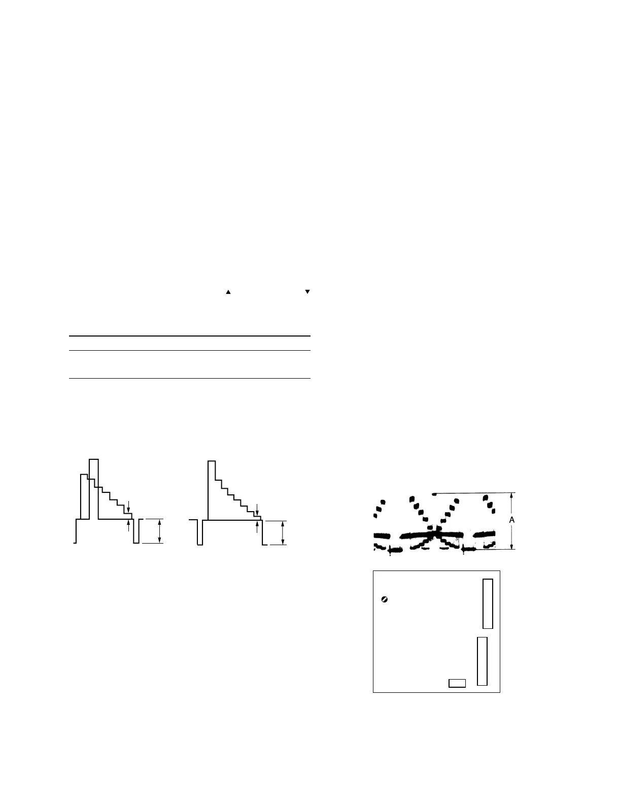
[for NTSC] [for PAL]
B
A
B
A
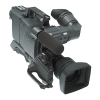
RV1
CN2
CN3
PA-187 (B) BOARD
PA-189 (R) BOARD
- A SIDE -
- A SIDE -
CN1