2-2
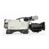
DXC-D30 (UC)
DXC-D30P (CE)
CAUTION
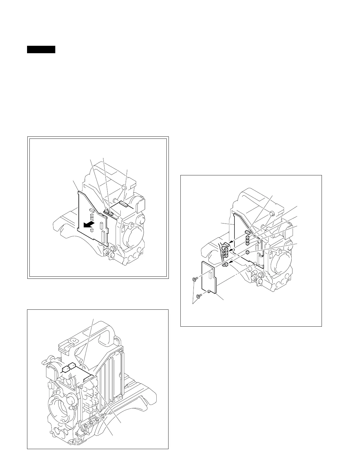
2-2-2. Cautions on Removal of Top Chassis
When removing the top chassis, following items should be
performed. If not, the connectors (CN503, CN504, CN505)
should be damaged.
1. Disconnect the two connectors CN504 and CN505 on the
CN-1195 board.
2. Remove the MB-629 board in the horizontal direction.
Because, not to break the connectors.
3. Disconnect the connector CN503.
4. Remove the SW-790 board.
CN-1195 board
CN503
SW-790
CN105
CN106
CN107
CN123
CN2
MB-629 board
AT-110 board
Screws(B3 X 4)
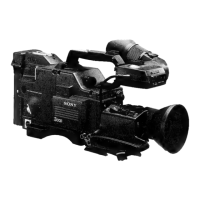
2-3. REPLACEMENT OF MAIN PARTS
2-3-1. Replacement of CCD Unit
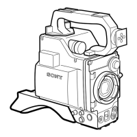
1. Remove the lens and viewfinder referring to the instruc-
tion manual.
Note: Attach a mount cap to the lens mount to protect the
prism block.
2. Remove the left side plate referring to Section 2-2-1.
“Removal of Side Plate”.
3. Remove two screws as shown in Figure.
Remove the AT-110 board. Disconnect the five connec-
tors CN2, CN105, CN106, CN107 and CN123 on the
MB-629 board.
CN505
CN504
MB-629 board
CN503