DXC-D30 (UC)
DXC-D30P (CE)
3-11
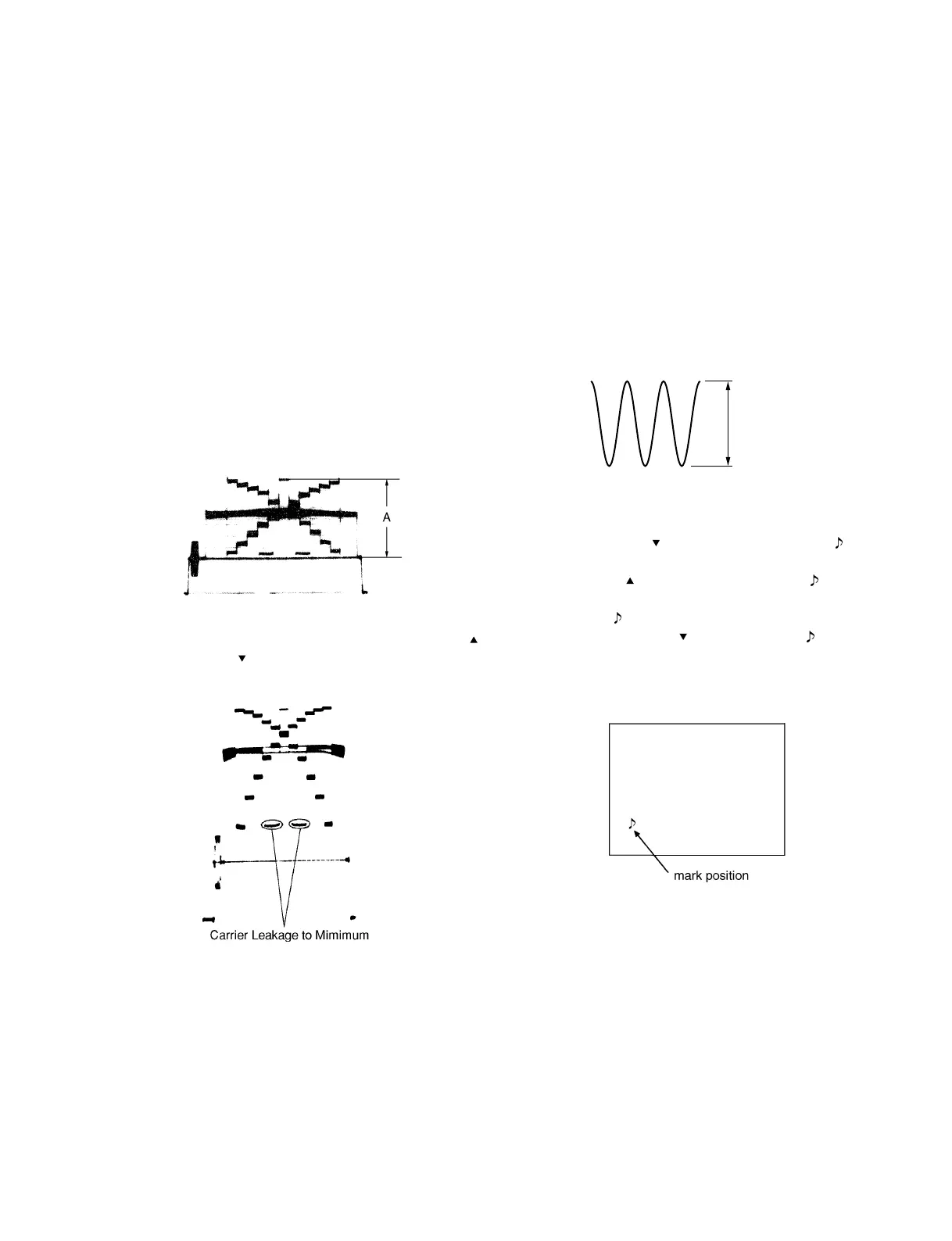
3-3-14. Flare Adjustment
Object: Grayscale chart
Equipment: Waveform monitor
Adjustment Procedure
1. SERVICE menu “PAGE 3”
→ R FLARE: x
G FLARE: 0
B FLARE: x
Note: Make sure that “G FLARE” must be “0”.
2. Chart frame = Underscanned monitor frame
3. Test point: VIDEO OUT connector/camera side
Adjusting point: Lens iris
Specification: A = 100 ± 2 IRE (for NTSC)
700 ± 10 mV (for PAL)
3-3-15. MIC LEVEL/MIC Level IND Adjustment
Equipment: Oscilloscope
Preparation: OUTPUT/DL/DCC + switch/camera side
→ BARS
Adjustment Procedure
1. Test point: CL201/MB-629 board
(GND: Capacitor, C202 + side/MB-
629 board)
Adjusting point: 1RV201/MB-629 board
2. SERVICE menu “PAGE 17”
→ MIC ADJ :
3. Adjust the DOWN
switch, and stop where the mark
just appears on the monitor screen.
4. Adjust the UP
switch, and step where the mark just
disappears on the monitor screen.
5. And, set the
mark to the value that subtract 5 time from
the value by DOWN
switch where the mark just
disappears.
Monitor screen or Viewfinder screen.
110 ± 5 mV
4. Open the lens iris by two steps.
5. Adjust “R FLARE” and “B FLARE” alternately by UP
switch or DOWN switch so that the carrier leakage level
is minimum.